Template Matching

|
This tool is only intended for use with G2 sensors. |

|
This tool is not supported on A and B revision Gocator 2100 and 2300 sensors that are not accelerated (either by a PC-based application or by GoMax). The tool is supported in emulator scenarios. |
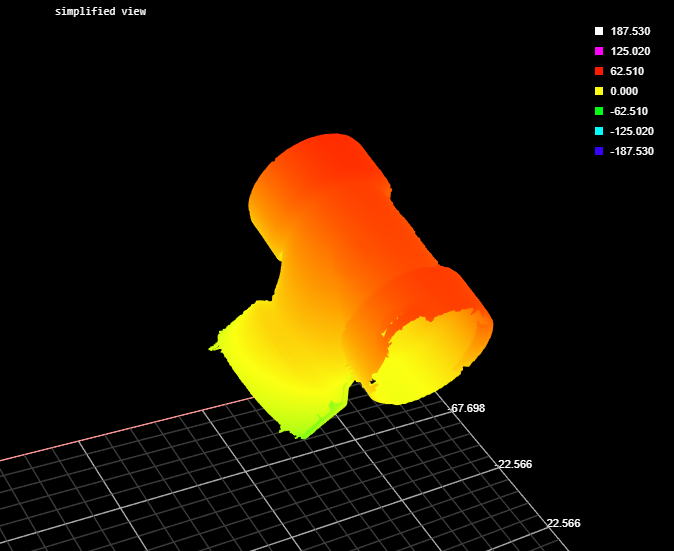
The Mesh Template Matching tool takes in Mesh scan data (produced by the Surface Mesh tool) and a template you previously defined based on a "golden part" (itself created using the Mesh Template Matching tool). The tool returns measurements related to the position and orientation of the scan data relative to the template, such as offsets and rotations, as well as standard deviations between the scan data and the template. The tool can also output Mesh scan data.


Measurements, Features, and Settings
| Measurement |
|---|
|
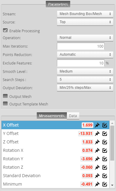
X Offset Y Offset Z Offset These measurements return the X, Y, and Z position of the center of the fitted bounding box, respectively. |
|
Rotation X Rotation Y Rotation Z The angle of the fitted bounding box around the X, Y, and Z axis, respecively. |
|
Standard Deviation The standard deviation of the data points from the fitted plane. |
|
Minimum Maximum The minimum and maximum error of the data points from the fitted plane, respectively. |
|
Deviation (x%) Deviations of the data points from the fitted plane, sorted into stepped percentiles. You set number of steps using the Output Deviation parameter. |
|
Processing Time The time the tool takes to run. |
| Type | Description |
|---|---|
|
Mesh |
The transformed Mesh. Only listed if the Output Mesh parameter is enabled. |
|
Mesh Template |
The template Mesh. Only listed if the Output Template Mesh parameter is enabled. |
| Parameter | Description |
|---|---|
|
Source |
The sensor |
|
Enable Processing |
When this option is enabled, the tool compares the Mesh data to the loaded template. |
|
Operation |
The tool's operation mode. One of the following:
|
|
Max Iterations |
The maximum number of iterations the tool uses to perform match the Mesh scan data with the template. Typically, leave this at the default value. |
|
Points Reduction |
Controls the number of points used in the matching process, which can improve processing time. |
|
Exclude Features |
Use this when there are high or low features on the part that should not be included in the matching. For example, at 10%, the tool excludes 10% of the points with maximum or minimum deviation from the matching process. |
|
Smooth Level |
The amount of smoothing the tool applies. LMI recommends leaving this setting at its default. |
|
Search Steps |
Determines the neighborhood level in which to search for connection point pairs. |
|
Output Deviation |
Determines which deviations are output as measurements, which can be a combination of minimum and maximum, and a set of Deviation (x %) measurements (with the specified step between them). Can also be set so that no deviations are output. Use this to get a rough idea of the distribution of the deviation values (or a histogram of the deviations). |
|
Filters |
The filters that are applied to measurement values before they are output. For more information, see Filters. |
|
Decision |
The Max and Min settings define the range that determines whether the measurement tool sends a pass or fail decision to the output. For more information, see Decisions. |