Using Bounding Box and Ellipse
When using a bounding box or an ellipse to match parts, the sensor tests whether a part fits into a bounding box or ellipse that you define. A match will occur regardless of orientation.
In the data viewer, a bounding box or ellipse is displayed with a blue outline. If a part fits in the bounding box or ellipse, any measurements configured on the Measure page are applied.
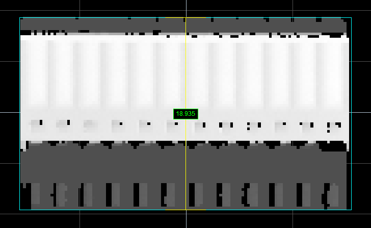
Blue bounding box around a part.
(Yellow lines show currently selected
dimension in Part Matching panel.)
Typically, setting up a bounding box or an ellipse to perform part matching involves the following steps:
- Scan a reference part (you can also use replay data that you have previously saved).
- Set the characteristics of the bounding box (width and length) or ellipse (major and minor axes).
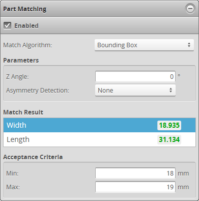
Part Matching panel (Bounding Box match algorithm)
The following settings are used to configure part matching using a bounding box or ellipse.
| Setting | Description |
|---|---|
| Match Algorithm | Determines which algorithm the sensor will use to attempt a match. |
| Z Angle | Corrects the orientation of the |
| Asymmetry Detection |
Rotates scans based on the asymmetry of the scanned part. The sensor calculates the number of points on each side of the part's centroid in the bounding box or ellipse. Along Major Axis – The scan is flipped so that the greater number of points is to the left. Along Minor Axis – The scan is flipped so that the greater number of points is on the bottom. None – The scan is not flipped. |
| Acceptance Criteria |
Determines the minimum and maximum acceptable values of the selected dimension (Width and Length for bounding box, Major and Minor for ellipse) in Match Result. |