Layout
The following sections describe the Layout category on the Manage page.

Mounting orientations must be specified for a dual- or multi-sensor system.

|
Dual |
|
|
For multi-sensor layouts with sensors angled around the Y axis, to get "side" data, you must uncheck Uniform Spacing before scanning. The Y offset, X angle, and Z angle transformations cannot be non-zero when Uniform Spacing is unchecked. Therefore, when aligning a sensor using a bar alignment target with Uniform Spacing unchecked, set the Degrees of Freedom setting to X, Z, Y Angle, which prevents these transformations from being non-zero. |
| Layout Type | Example | |
|---|---|---|

|
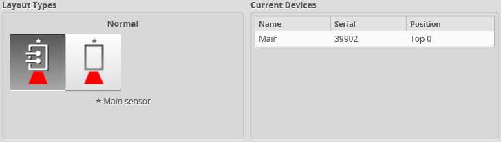
Normal The sensor operates as an isolated device. |
|

|
Reverse The sensor operates as an isolated device, but in a reverse orientation. You can use this layout to change the handedness of the data. |
|

|
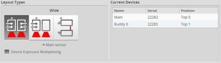
Wide Sensors are mounted in Left (Main) and Right (Buddy) positions. |
|

|
Reverse Sensors are mounted in a left-right layout as with the Wide layout, but the Buddy sensor is mounted such that it is rotated 180 degrees around the Z axis to prevent occlusion along the Y axis. Sensors should be shifted along the Y axis so that the laser lines align. |
|

|
Opposite Sensors are mounted in Top (Main) and Bottom (Buddy) positions |
|

|
Grid For systems composed of three or more sensors. Sensors can be mounted in a 2-dimensional grid using the settings in the Layout Grid area below. Side-by-side and top-bottom configurations are supported, as well as combinations of these and reversed orientations. |
|


To specify a standalone layout:
|
|||
See the table above for information on layouts. |
|
|
Before you can select a dual-sensor layout, you must assign a second sensor as the Buddy sensor. |
To specify a dual-sensor layout:
|
|||
See the table above for information on layouts. |
|
|
Before you can select a multi-sensor layout, you must assign two or more additional sensors as Buddy sensors. |
To specify a multi-sensor layout:
|
|||
The Main sensor is automatically assigned to the first cell. You can however assign the Main sensor to any cell. |
|||
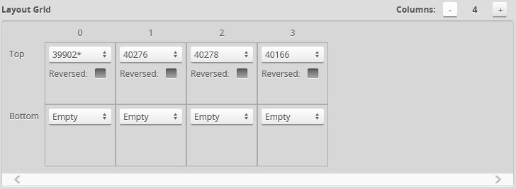
The following shows the layout of a four-sensor Wide system:
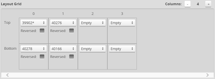
The following shows the layout of a four-sensor system, with two sensors on the top and two sensors on the bottom:
See the table above for more information on layouts. |
|||
|
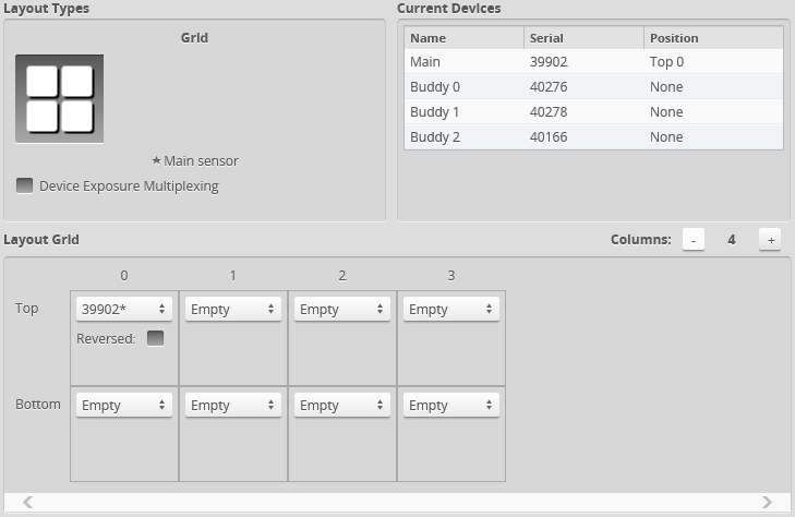
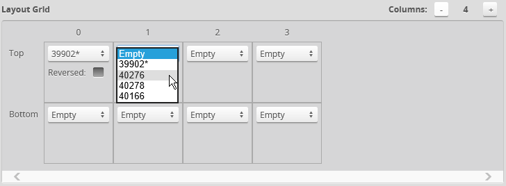
You must assign all Buddy sensors to a cell in the layout grid. Otherwise, the system will not run.
You can configure dual- and multi-sensor systems so that there is a slight delay between the exposures of sensors or groups of sensors to eliminate laser interference, using the Device Exposure Multiplexing setting. For more information, see Device Exposure Multiplexing.