Merge Wide

|
This tool is not supported on A and B revision Gocator 2100 and 2300 sensors that are not accelerated (either by a PC-based application or by GoMax). The tool is supported in emulator scenarios. |
|
|
This tool is only intended for use with G2 sensors. |
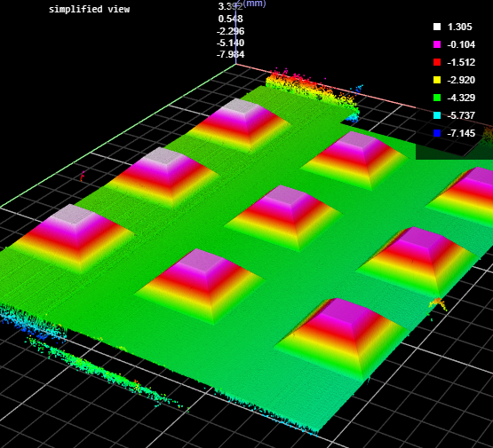
The Surface Merge Wide tool uses an XML transformation file produced by the Surface Align Wide tool (see Wide Layouts (Surface Align Wide Tool)) and combines scan data from multiple sensors into a single surface. You can use any built-in or GDK-based Surface measurement tool to perform measurements on the resulting merged Surface scan data.
| Measurement |
|---|
|
Processing Time The time the tool takes to run. |
| Type | Description |
|---|---|
|
Processed Surface |
The Surface data resulting from combining the scan data of the individual sensors. You can use any Surface measurement tool to perform measurements on the combined data. |
| Parameter | Description |
|---|---|
|
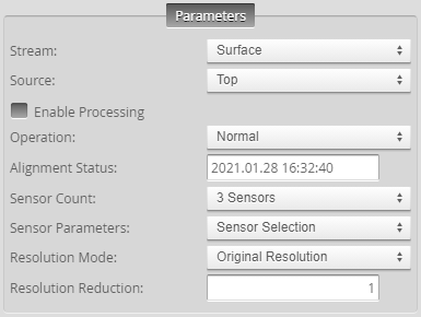
Source |
The sensor |
|
Enable Processing |
Causes the tool to start merging data from the individual sensors. Make sure to properly configure the tool before enabling this option. |
|
Operation |
Actions that apply to the XML initialization file the tool will use to perform merging. An initialization file must first be created by Surface Align Wide (see Wide Layouts (Surface Align Wide Tool). XML files are located in C:\GoTools\SurfaceAlign. One of the following:
|
|
Alignment Status |
Indicates whether the tool has aligned the sensors. Either "Not Aligned" or the date of the alignment. |
|
Sensor Count |
Indicates the number of sensors in the system. |
|
Sensor Parameters |
A drop-down that lets you display the settings of a specific sensor. You do not usually need to change these settings, as they are set when you load the XML file produced by Surface Align Wide using the Operation drop-down. The values are intended for diagnostics only. For information on the parameters, see Sensor Parameters. |
|
Y Axis Used |
When enabled, displays a Y Scaling setting. For more information, see below. |
|
Y Scaling |
Typically used to compensate for errors in encoder settings, which can distort scan data. If you cannot change the encoder settings or if you are working with data recorded with an incorrectly configured encoder, use this setting to adjust the Y scaling to compensate. The value used in this tool must match the value used in Surface Align Wide (see Wide Layouts (Surface Align Wide Tool). Only displayed when Y Axis Used is enabled (see above). |
|
Resolution Mode |
Determines whether the tool scales the X or Y resolution so that they are the same (a 1:1 ratio), or leaves the X and Y resolutions as the original. One of the following.
|
|
Resolution Reduction |
Reduces the lateral resolution of the heightmap to reduce processing time. |
|
Filters |
The filters that are applied to measurement values before they are output. For more information, see Filters. Not typically used with this tool. |
|
Decision |
The Max and Min settings define the range that determines whether the measurement tool sends a pass or fail decision to the output. For more information, see Decisions. Not typically used with this tool. |
| Parameter | Description |
|---|---|
|
Y Offset Buffering |
Displayed when Resolution Mode is set to Customized. The Y Offset Buffering setting determines how the input surface data from sensor layouts with sensors offset along the Y axis is handled over multiple subsequent input surfaces. The following options are available: Disabled The tool performs no offset buffering. This mode is suitable if some sensors in the system are offset along Y, but the motion is cyclic (back-and-forth), such as a motion stage, and not a conveyor. The resulting output surface will not have straight edges on the top and bottom due to the Y offset between the input surfaces. Fixed Length The tool buffers some of the input surface data from one frame to be merged with the data from the subsequent input frames. Use this mode in continuous scanning applications, such as with a conveyor, and if some sensors in the sensor system are offset along the Y axis and the system uses Fixed Length surface generation to ensure that the complete, combined Surface scan is output. (For more information on Fixed Length surface generation, see Surface Generation.) The tool outputs the new surface data in the Processed Surface data output. Choosing this option displays two additional, optional parameters: Overlap Length and Reset Time Limit.
|

