Wide Layouts (Surface Align Wide Tool)

|
This tool requires PC-based acceleration. |
|
|
The tools described in the following sections are only intended to be used with G2 sensors. |
|
|
LMI strongly recommends disabling Uniform Spacing on the Scan page for the alignment procedure, as this will simplify the configuration of the alignment tools. (For more information on configuring uniform spacing, see Scan Modes.) After you have completed the alignment procedure, you can enable Uniform Spacing if your application requires it: the setting does not have to match between the alignment procedure and in jobs you use in production. |
The Surface Align Wide tool aligns a multi-sensor system with two or more sensors in a wide (side-by-side) layout and saves the transformations for each sensor in an XML file. Unlike alignment performed using the Alignment panel on the Scan page, the tool determines the X angle rotation (for information on coordinate systems, see Profile Output), giving you a full six degrees of freedom. This method of alignment will produce higher accuracy scans, and allows for higher scan rates, due to the use of a different algorithm when the sensor combines data from multiple sensors.
Note that in order to perform scans and measurements in production using a system aligned using this tool, you must include the Surface Merge Wide tool (see Merge Wide) in your scanning job, loading the transform XML file created by this tool into the merging tool, to combine the scans from the individual sensors into single frames of Surface scan data. You can then apply any built-in or custom GDK-based Surface tools to the resulting processed data (see Surface Measurement).
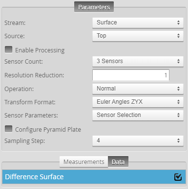
After configuring the tool (see below), you must check the Enable Processing checkbox to start processing. After the tool has finished processing the data, it produces the XML file you load into a Surface Merge Wide tool, as well as a Difference Surface data output that you can use to assess the quality of the alignment.
Note that after aligning using this tool, on the Alignment panel on the Scan page, Gocator indicates that the sensors are unaligned. This is expected.
Alignment Target and Setup
This alignment tool requires the use of a pyramid plate alignment target, which consists of rows and columns of truncated pyramid forms. You can find CAD files for a 3x3 pyramid target under Tools\Alignment CAD\Pyramid Plate in the Utilities package (e.g., 14405-x.x.xx.xx_SOFTWARE_GO_Utilities.zip, available on LMI's Product Downloads page).
|
|
The alignment target LMI provides in a CAD file is appropriate for sensors angled up to roughly 15° from vertical. For information on alignment target requirements, see below. |

A 3x3 pyramid plate. Exact dimensions of the plate and the pyramids will depend on the sensors in your system.
The following requirements should be satisfied for best results:
-
Make sure the alignment target surface is not too shiny or too dark to be scanned.
-
Edges do not need to be perfectly sharp: The alignment tool performs a plane fit to points within the planar surfaces and excludes data close to the edges.
-
For highest accuracy, use a target sized so that each sensor covers the area of only one column. However, if an application requires that sensors must be angled so that their laser planes mostly overlap, two sensors can see the same column.
-
Pyramid heights should be at least 1/5 of the measurement range of the sensor. For example, the measurement range of a Gocator 2520 is 25 mm; for this type of sensor, the pyramid height should be at least 5 mm. (For measurement range specifications, see Sensors.)
-
Pyramid tops should be at least 1/10 of the sensor's FOV, taking into account the location of the target along the Z axis in the sensor's measurement range. For example, at the midpoint in the measurement range of a Gocator 2520, the FOV is 28.75 mm; for this type of sensor, the pyramid tops should be at least 2.875 mm along each side.
-
The pyramid angle (the angle between the side planes and the base plane) must be greater than 30°.
-
Pyramid sides should preferably not be angled from a sensor's Z axis by more than 60 degrees. So for example, if you use an alignment target with 45° pyramid sides, a sensor's Z axis shouldn't be angled by much more than 15 degrees from vertical. For sensors angled 30 degrees from vertical, for example, an alignment target whose pyramid sides are angled only 30 degrees would be more appropriate.
-
Maximize the target size to ensure that as much of the base area is visible to the sensor. Keep in mind however that the target size should be smaller than the FOV.
-
The flat area at the base of the pyramids must be visible to the sensors.
-
Only one row of pyramids is required for the alignment procedure, but using additional rows improves the accuracy of the alignment.
-
Pyramids should be roughly centered in the FOV of each sensor.
-
For best results, all four sides of a pyramid should be visible to a sensor.
-
Given the size of the top widths of the pyramids and the distance of the sensors to the alignment target, the top widths should be represented by a minimum of 100 to 200 data points along the X axis in the scan data.
-
Flatness should be roughly the Z resolution of the sensor.
-
To maximize the accuracy of the alignment, block any unwanted planar data during scanning, such as the conveyer belt beneath the target. To do this, you can shrink the sensor’s active area in the Acquire > Scan page to exclude this data while scanning the target. Remember to reset the active area after the alignment. For more information on setting the active area, see Active Area.
-
After you have scanned the alignment target, verify in the scan data that each of the five planar segments of each pyramid (the top and the four sides) is represented by at least 100 x 100 data points. If the point count along the X axis is less than 100, one alternative way is to scan the target in a smaller Y Spacing to meet the 100 x 100 points per segment threshold.
Procedure Overview
The following provides an overview of the steps involved in performing a high-accuracy, tool-based alignment.
To perform the alignment:
| 1. | Set up and configure the multi-sensor system. |
The following sections describe setting up and configuring a system:
| 2. | Fabricate an alignment target appropriate for your system (wide or side-by-side layout versus ring layout). |
For details on the alignment target, see Alignment Target and Setup.
|
|
Although you can scan the alignment target without acceleration, you must perform the alignment using PC-based acceleration (for more information, see Software-Based Acceleration). Because starting acceleration after having performed a scan clears scan data from a sensor, if you are going to perform alignment on-sensor, you should start acceleration before continuing. You can also optionally download the sensor state and scan data as an emulator scenario and perform the alignment on the scanned target using the emulator. For more information, see Downloading a Support File and Running the Emulator. |
|
|
Make sure you have decided whether to enable or disable Uniform Spacing on the Scan page before proceeding. For important information, see Using Uniform Spacing During the Alignment. |
| 3. | Enable recording by clicking the Record button. |

| 4. | Start the transport system and then perform a scan of the alignment target. |
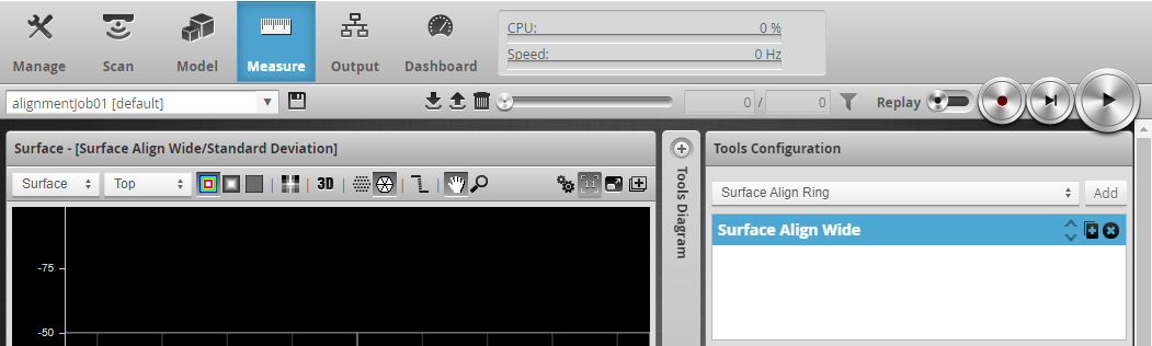
| 5. | On the Measure page, add a Surface Align Wide tool. |
| 6. | If you have a "Start" initialization file (see above), choose Load from the Operation drop-down, load that file, and go to step 10. |
| 7. | Set Sensor Count to the number of sensors in the system. |
| 8. | Under Sensor Parameters, select the sensors, one by one, and configure the parameters related to the sensor's position. |
For more information, see Sensor Parameters.
| 9. | Check Configure Pyramid Plate and configure the parameters related to the alignment target. |
For more information, see Pyramid Plate Configuration Parameters.
| 10. | Configure the alignment tool's remaining parameters and enable the diagnostics data outputs (on the tool's Data tab) if needed. |
| 11. | Check the Enable Processing checkbox. |
The tool processes the scan data, using the provided sensor transformations and alignment target configuration, and saves an XML transformation file to C:/GoTools/SurfaceAlign. If the alignment process succeeds, the Calibration Status field displays the time and date of the alignment.
You must the load the resulting XML file in a Surface Merge Wide tool, typically in a separate job, which transforms and merges the multi-sensor scan data into a common coordinate system. You can then apply other measurement tools to the merged scan data. For more information on the merging tool, see Merge Wide.
Measurements, Data, and Parameters
| Measurement |
|---|
|
Standard Deviation Alignment uncertainty (an indicator of alignment quality). |
|
X Origin{n} Y Origin{n} Z Origin{n} The X, Y, and Z transformations calculated for sensor {n}. |
|
X Angle {n} Y Angle {n} Z Angle {n} The X, Y, and Z angle transformations calculated for sensor {n}. |
|
Processing Time The time the tool takes to run. |
| Parameter | Description |
|---|---|
|
Source |
The sensor |
|
Enable Processing |
Causes the tool to perform the alignment. If the alignment is successful, the tool creates an XML alignment (calibration) file containing the transformations of the sensors that you must use with the Surface Merge Wide tool when scanning production targets to merge scan data. Make note of the XML file indicated in the log pane for use with Surface Merge Wide. Make sure to properly configure the tool before enabling this option. Disable it after performing the alignment; otherwise, the tool will continue performing the alignment on new frames of data, which will have an impact on performance. |
|
Operation |
Actions that apply to the tool's XML initialization files. One of the following:
|
|
Sensor Count |
Indicates the number of sensors in the system. |
|
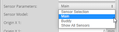
Sensor Parameters |
A drop-down that displays the settings of the selected sensor. For descriptions of the individual sensor parameters used for the alignment, see Sensor Parameters. |
|
Y Axis Used |
When enabled, displays a Y Scaling setting. For more information, see below. |
|
Y Scaling |
Typically used to compensate for errors in encoder settings, which can distort scan data. If you cannot change the encoder settings or if you are working with data recorded with an incorrectly configured encoder, use this setting to adjust the Y scaling to compensate. The value used in this tool must match the value used in Surface Merge Wide (see Merge Wide). Only displayed when Y Axis Used is enabled. |
|
Configure Pyramid Plate |
If enabled, displays parameters that let you configure the pyramid plate's specifications. For descriptions of the pyramid plate parameters, see Pyramid Plate Configuration Parameters. For information on alignment targets, see Alignment Target and Setup. |
|
Transform Format |
The transformation format the tool uses. Typically, you can leave this at its default setting. Choosing a different format may be useful if you need to compare what the sensors detect to the transformation format used in your CAD package, for example. The setting does not affect alignment. One of the following:
|
|
Alignment Mode |
The coordinate system used in the aligned system. In both cases, the Y axis is in the direction of motion. One of the following: Sensors The resulting Y rotation of sensors is such that the average Y rotation is 0. The origin of the coordinate system is at the average sensor center position. Sensors with Target Tilt The resulting Y rotation of sensors is such that the target surface is aligned to be horizontal. This mode is recommended when aligning to a conveyor on which the target is placed flat. The origin of the coordinate system is at the average sensor center position. |
|
Sampling Step |
The step in data points in both directions with which the surface is processed. Choosing a higher sampling step reduces the processing time the tool requires, but reduces fit accuracy. Useful if the surface being processed has a large number of data points. Typically, you will want to use as low high a sampling step as possible; use a high sampling step only for initial testing purposes. |
|
Resolution Reduction |
Reduces the lateral resolution of the heightmap to reduce processing time. |
|
Filters |
The filters that are applied to measurement values before they are output. For more information, see Filters. Not typically used with this tool. |
|
Decision |
The Max and Min settings define the range that determines whether the measurement tool sends a pass or fail decision to the output. For more information, see Decisions. Not typically used with this tool. |
| Parameter | Description |
|---|---|
|
Sensor Model
|
Sets the sensor's model. |
|
Origin X {n} / Origin Y {n} |
The X and Y origin of sensor {n}. In order for the alignment to succeed, you must enter the rough spatial relationship between the sensors. The estimated X and Y position of the intersection of the sensor's Z axis with the pyramid plate, relative to the center of a bounding box that encompasses the intersections of all sensors in the system. The accuracy of the values should be at least 1/10 the distance between pyramids. So, for example, with a distance of 25 mm between pyramids, the minimum accuracy is of these values is 2.5 mm. For more information, see Setting Origin X and Origin Y. |
|
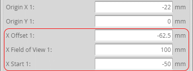
X Offset {n} X Field of View {n} X Start {n} |
These parameters are only displayed if Uniform Spacing is enabled. For more information, see Using Uniform Spacing During the Alignment. |
Setting Origin X and Origin Y
The Origin X {n} and Origin Y {n} settings in the Surface Align Wide tool represent the estimated, real-world, X and Y position of the intersection of a sensor's Z axis with the flat surface of the pyramid plate, relative to the center of a bounding box that encompasses the intersections of all sensors in the system.
For example, in the following example of a two-sensor system, with the sensors placed side by side (no displacement along the Y axis), the X position of the intersection of the left sensor's Z axis and the alignment target's flat surface is roughly -25 mm, and the X position for the right sensor is 25 mm. You would use these values in the Surface Align Wide tool's Origin X 1 (for the left sensor) and Origin X 2 (for the right sensor) parameters, respectively.

In the following, a three-sensor system with sensors positioned at different Y locations (viewed from above), the Origin X and the Origin Y value of each sensor is set to the distance (X and Y position) of the intersections between the alignment target surface and the sensors' Z axes, relative to the center of the bounding box that encompasses the intersections.

Note however that for sensor systems with sensors positioned at different Y locations, you can set Origin Y {n} to 0 if the entire alignment target is scanned during the alignment procedure: the algorithm uses the edges of the alignment target to determine the Y component of the sensors' origin. If you do not scan the entire alignment target during the procedure, you must enter an estimate of the Y position of the sensors' origins.
|
|
It is very important to consult the specifications of the sensors in your system to determine the direction of X and Y. In multi-sensor systems, the Y axis is determined by the Main sensor's orientation. |
If your application requires that sensors be angled, remember to take this into account when estimating the values needed for Origin X and the Origin Y, paying attention to where the Z axis of each sensor intersects with the alignment target's lower flat surface.
Using Uniform Spacing During the Alignment
If you choose to enable Uniform Spacing during the alignment, you must perform these additional steps. Otherwise, the alignment will fail.
These steps separate the individual sensors' scan data in the heightmap so that the alignment tool can process the scan data from each sensor individually. To do this, you set artificial offsets along the X axis to separate the scan data so that there is no overlap between the sensors.
Do the following:
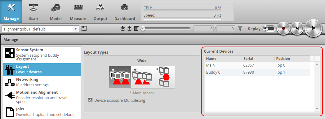
| 1. | (Optional) In the web interface, go to the Manage page, click the Layout section, and make note of the names, serial numbers, and positions listed in the Current Devices table. |
This information will be useful when you continue configuring the system in other parts of the web interface.
| 2. | In the web interface, go to the Scan page, expand the Sensor panel, and in that panel, expand the Transformation area. |
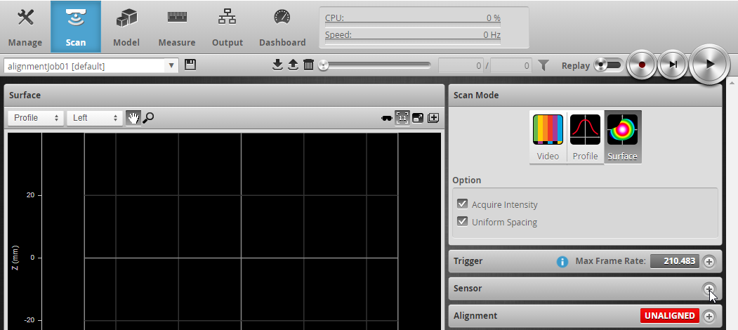
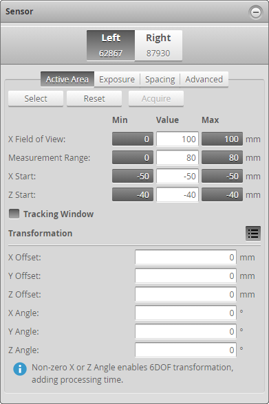
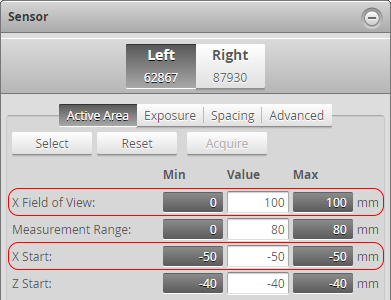
| 3. | For each sensor in the system, in the Active Area tab, make note of the values for X Field of View and X Start. |
For example in the image below, for the "Left" sensor (serial number 62867), copy the values of "100" and "-50" in the Value fields.
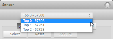
Note that in multi-sensor systems (containing more than two sensors), sensors are instead listed in a drop-down:
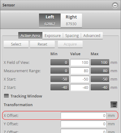
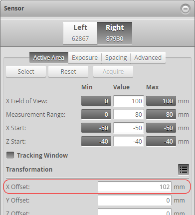
| 4. | For each sensor in the system, in the Transformation area, set X Offset to a value that eliminates any overlap between sensors, and make note of this value. |
For example, for sensors with a 100 mm field of view, you might choose 1 or 2 mm for a blank area. Therefore, for the Left sensor, you could set its X Offset 0 mm.
For the Right sensor, you could set its X Offset to 101 or 102 mm.
For systems with more than two sensors, simply set the offsets to ensure that the individual sensors' scan data in the heightmap does not overlap.
| 5. | Go to the Measure page and add an instance of Surface Align Wide. |
| 6. | For each sensor, select the sensor you need to configure in the Sensor Parameters drop-down and copy the "X Field of View," "X Start," and "X Offset" values from the Scan page into the corresponding parameters in the alignment tool. |
Choosing the sensor to configure:
Entering the values copied from the Scan page into the corresponding parameters in the tool:
Make sure to do this for each sensor.
| 7. | If you have not already done so, finish configuring the rest of the tool's parameters. |
Note that the artificial offsets you use to create the combined heightmap for the alignment procedure are unrelated to the values you need to use in Origin X {n}; for more information on this setting, see Setting Origin X and Origin Y.