Surface Generation
The sensor can generate a
The sensor uses different methods to generate the data, depending on the needs of the application. Data generation is configured in the Surface Generation panel on the Scan page.
|
|
|
|
|
|
The types in the table below correspond to the Type setting in the panel.

|
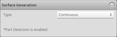
When Type is set to Continuous, part detection is automatically enabled. When Type is set to any of the other settings, part detection can be enabled and disabled in the Part Detection panel. For descriptions of the settings that control part detection logic, Part Detection. |
|
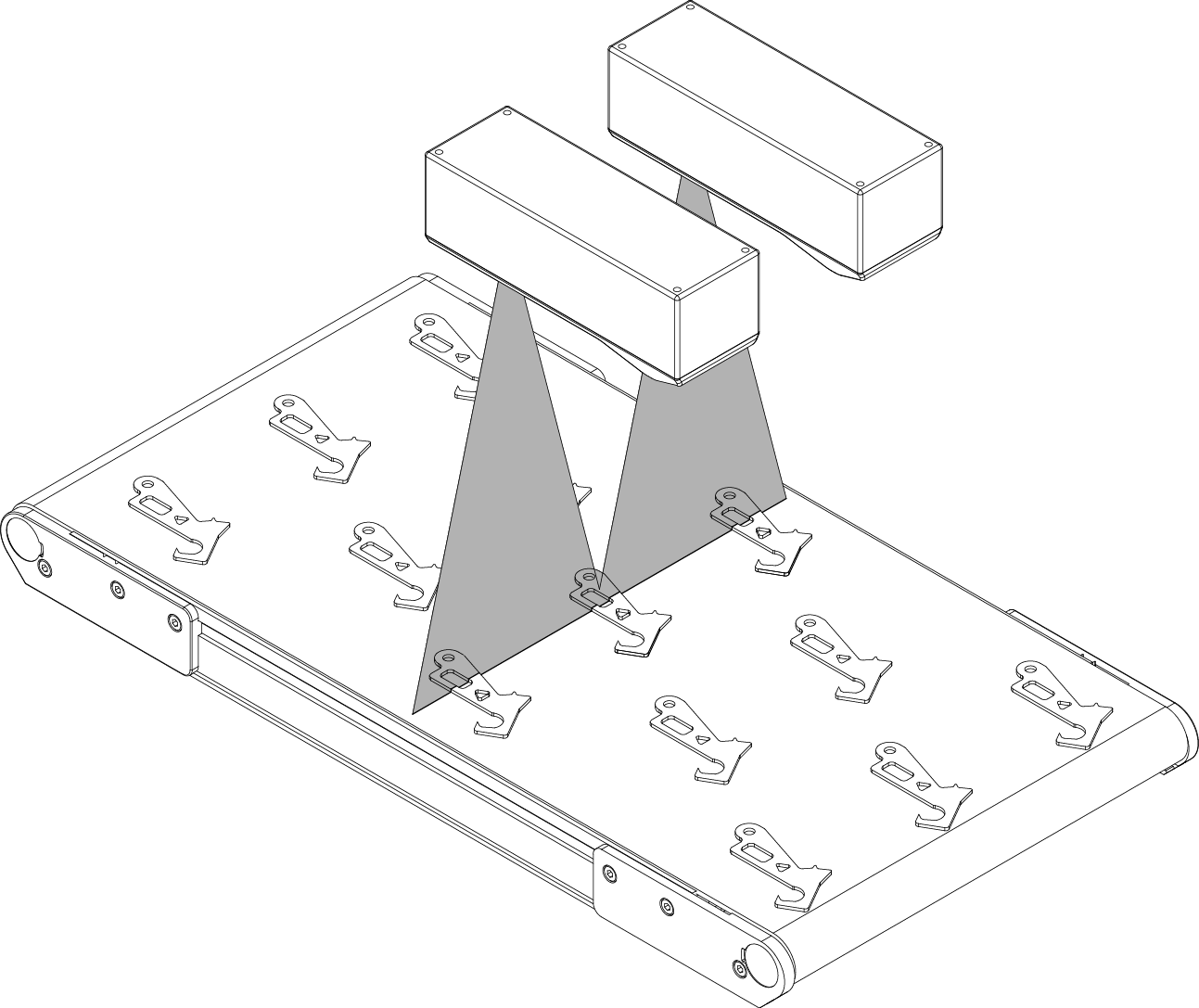
Continuous: The sensor continuously generates |
|
||
|
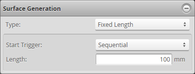
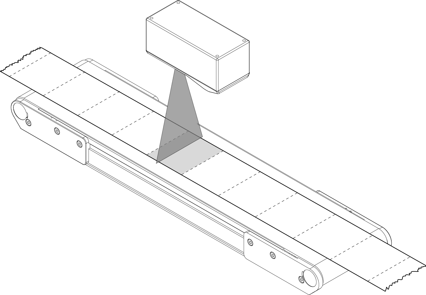
Fixed Length: The sensor generates For correct length measurement, you should ensure that motion is calibrated (that is, encoder resolution for encoder triggers or travel speed time triggers). The following types of start triggers are available under Start Trigger:
For more information on connecting external input to a sensor, see Digital Input. You can optionally enable part detection to process the |
|
||
|
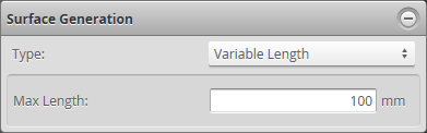
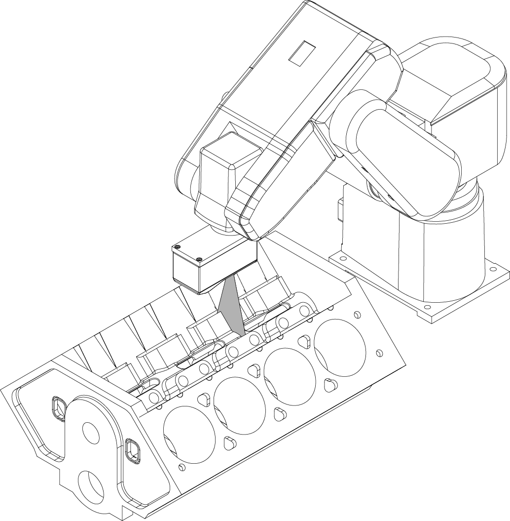
Variable Length: The sensor generates For correct length measurement, you should ensure that motion is calibrated (i.e., encoder resolution for encoder triggers or travel speed for time triggers). For more information on connecting external input to a sensor, see Digital Input. You can optionally enable part detection to process the |
|
||
|
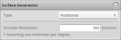
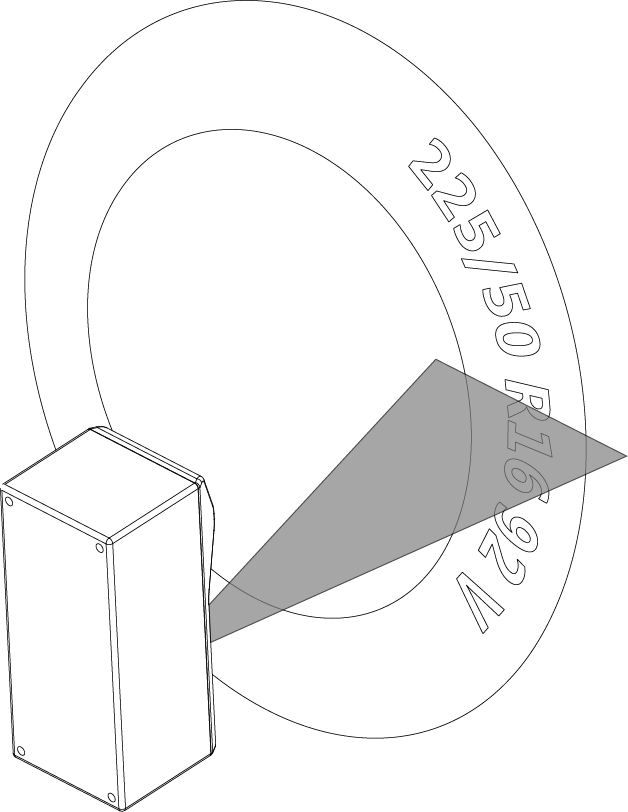
Rotational: The sensor reorders
You can optionally enable part detection to process the |
|
To configure
If this mode is not selected, you will not be able to configure surface generation. |
|||
|
|||
See the types and their settings described above. |
 button.