Mesh

|
This tool is not supported on A and B revision Gocator 2100 and 2300 sensors that are not accelerated (either by a PC-based application or by GoMax). The tool is supported in emulator scenarios. |
|
|
This tool is only intended for use with G2 sensors. |
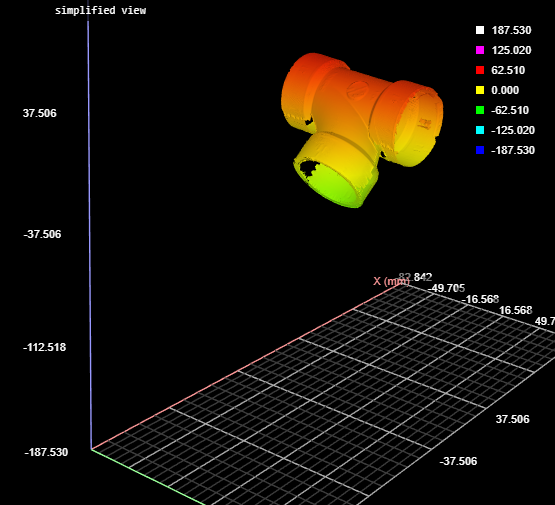
The Surface Mesh tool takes in an XML transformation file produced by the Surface Align Ring tool (see Ring Layouts (Surface Align Ring Tool)), and stitches scan data from multiple sensors into a single mesh, which is typically a 360-degree scan. (That is, when sensors are in a ring configuration.) You can apply some measurements directly to the resulting Mesh scan data, or you can use the Mesh Projection tool to extract a surface from any angle of the Mesh data, and apply any of the other Surface measurement tools to the extracted surface.
Note that the tool's settings (most of which are visible only if you select a sensor from the Sensor Parameters drop-down) are populated by loading the XML transformation file produced by Surface Align Ring.
|
|
If you have configured the layout so that some sensors are located in the bottom row of the layout grid, make sure to select Top & Bottom in Source when using this tool. For more information on layouts, see Layout. |
| Measurement |
|---|
|
Detected Sensor Count The number of sensors detected in the system. |
|
Processing Time The time the tool takes to run. |
| Type | Description |
|---|---|
|
Mesh |
The Mesh data resulting from combining the scan data of the individual sensors. This data output can be taken as input by the Mesh tools (see Mesh Measurement). Use Mesh Projection or Mesh Plane to extract Surface data from this output, which can then be measured using any Surface measurement tool. |
| Parameter | Description |
|---|---|
|
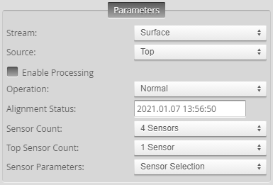
Source |
The sensor |
|
Enable Processing |
Causes the tool to start processing scan data from individual sensors, combining it into a Mesh data output. Make sure to load the XML |
|
Operation |
Actions that apply to the tool's XML initialization files. XML files are located in C:\GoTools\SurfaceAlign. One of the following:
|
|
Alignment Status |
Indicates whether the tool has aligned the sensors. Either "Not Aligned" or the date of the alignment. |
|
Sensor Count |
Sets the number of sensors in the system. |
|
Top Sensor Count |
Sets the number of sensors in the Top position in the system. |
|
Invert Y Direction |
Converts from a left-handed coordinate system to a right-handed coordinate system. Typically, it should always be enabled. |
|
Sensor Parameters |
A drop-down that lets you display the settings of a specific sensor. You do not usually need to change these settings, as they are set when you load the XML file produced by Surface Align Ring using the Operation drop-down. The values are intended for diagnostics only. For information on the parameters, see Sensor Parameters. |
|
Smoothing |
If enabled, applies smoothing to each sensor’s frame before stitching them together. Set the smoothing level in Smooth Window. For low density surfaces, you should disable smoothing to preserve the edge details. |
|
Smooth Window |
Sets the smoothing level. |
|
Maximum Mesh Tilt |
The maximum acceptable angle between a sensor's XY plane and the generated mesh triangles. Using a smaller value can result in a cleaner transition where the Surface scan data of individual sensors are stitched, reducing the inclusion of outlier data points or the creation of artifacts. |
|
Distance tolerance |
The maximum acceptable distance between the data points in overlapping Surface data. |
|
Filters |
The filters that are applied to measurement values before they are output. For more information, see Filters. Not typically used with this tool. |
|
Decision |
The Max and Min settings define the range that determines whether the measurement tool sends a pass or fail decision to the output. For more information, see Decisions. Not typically used with this tool. |