Transform
The Surface Transform tool generates a new surface based on the coordinate system of geometric features the tool uses as input. The tool can take a zero-plane, line, and origin point to define this new coordinate system. You can then apply the built-in measurement tools or GDK tools to this new surface data. This could let you, for example, get the height of a feature relative to a slightly tilted or warped adjacent or surrounding reference surface, rather than the absolute height in the original scan volume relative to the sensor. The result is increased repeatability of your measurements.
|
2D View |
3D View |
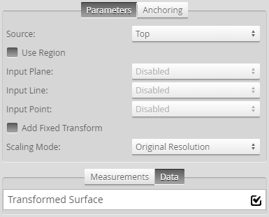
Measurement Panel
In Combinations of geometric feature inputs and results, the following geometric features are used by a Surface Transform tool in various combinations (a plane, a line, and a point).
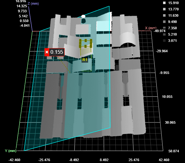
A Surface Plane tool, with the region set to a small left-facing angled surface

A Surface Edge tool, with the region set to the left edge of a raised surface (upper left of data viewer).
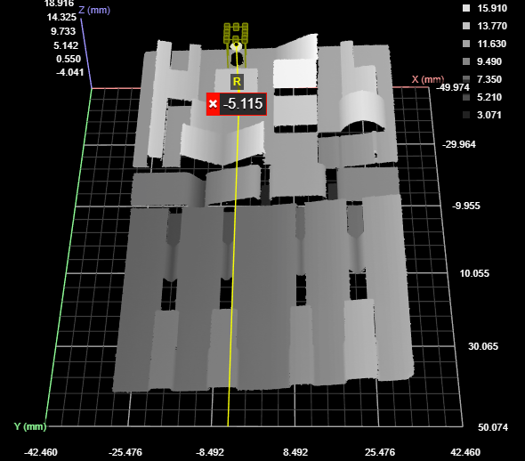
A Surface Position tool (maximum Z), with the region set to the raised point near the top of the data viewer.
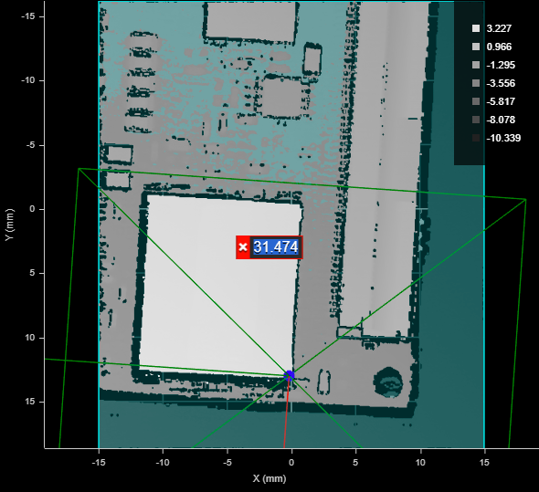
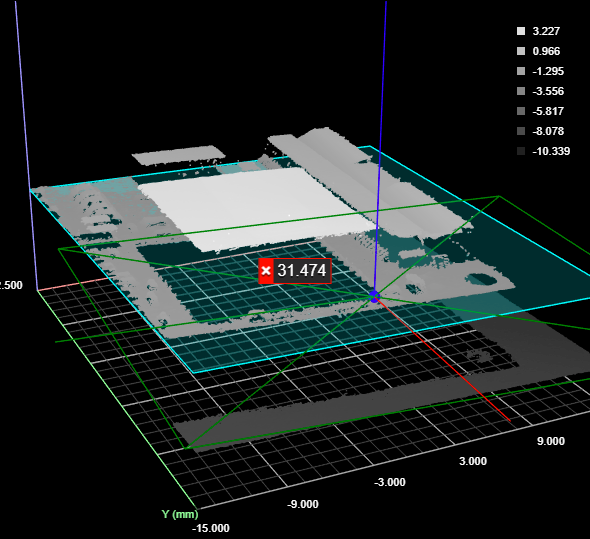
Furthermore, in the sections below, two types of data are shown: the original (input) scan data and the transformed data. When the tool displays the original data, it overlays indicators of the new, transformed coordinate system on the data.
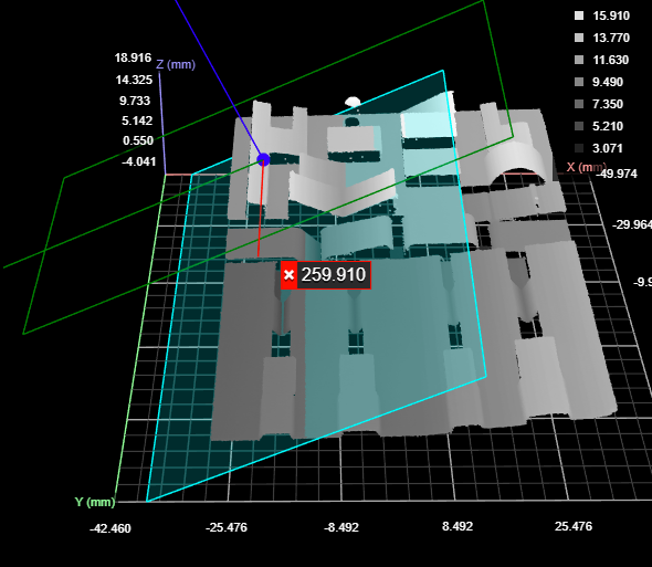
A Surface Transform tool using all three types of geometric feature inputs.
The data viewer is set to display the input surface data with an overlay of the transformed coordinate system.
In the data viewer, the following is displayed:
X, Y, and Z axes
The transformed axes are represented above by the red, green, and blue lines intersecting on the surface data above. Note how these are rotated with respect to the original coordinate system (the background grid, axes, and values along the axes).
Origin
The new origin is represented by the dark blue dot at the intersection of the transformed axes.
Plane
The new plane is represented by the cyan rectangle.
Bounding box containing the transformed surface
The bounding box that indicates where the transformed data is in relation to the original coordinate system.

|
To switch between the original and transformed data, choose Surface or Tool in the first drop-down above the data viewer, respectively. |
Combinations of geometric feature inputs and results
The Surface Transform tool accepts all combinations of input geometric features (plane, line, and point). For details and examples of each, see the following sections.
Plane
| New Z=0 XY Plane | New X Axis | New Origin |
|---|---|---|
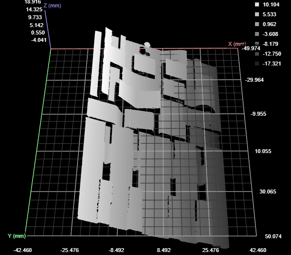
| Matches the input plane. | Parallel to the old X axis. | Old origin projected to plane. |
Original data with overlay
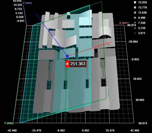
Transformed data
Line
| New Z=0 XY Plane | New X Axis | New Origin |
|---|---|---|
| The new plane contains the line. The intersection of the new plane and the old plane is perpendicular to the input line. | Matches the line. | Old origin projected onto the line. |
Original data with overlay
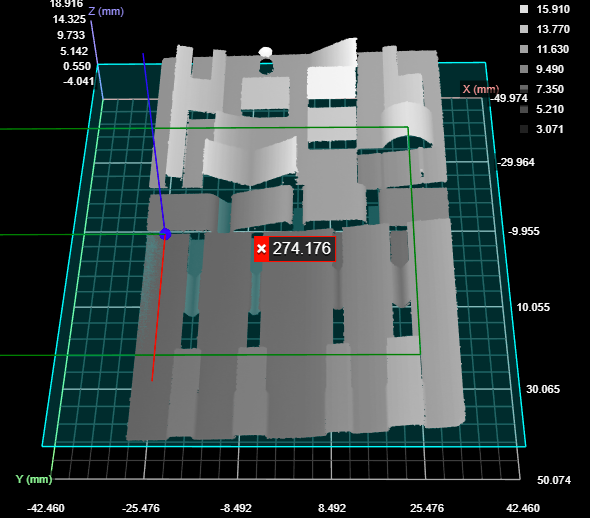
Transformed data
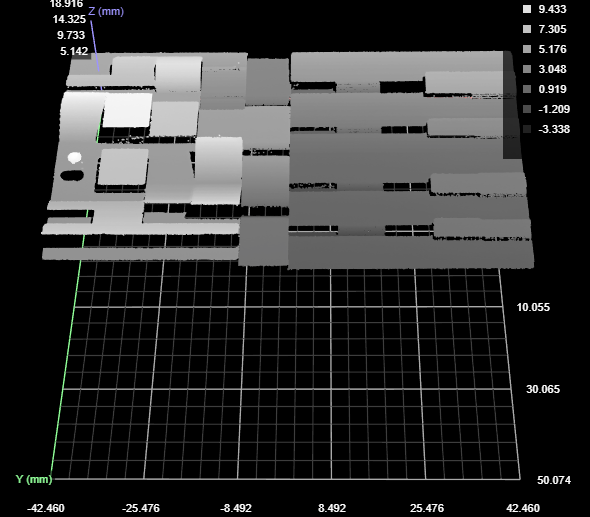
The direction of the X axis depends on the tool generating the line that Surface Transform takes as input. You may need to adjust the direction using the Add Fixed Transform settings.
Point
| New Z=0 XY Plane | New X Axis | New Origin |
|---|---|---|
| Through the input point, parallel to old Z=0 plane. | Parallel to the old axis. | The input point. |
Original data with overlay
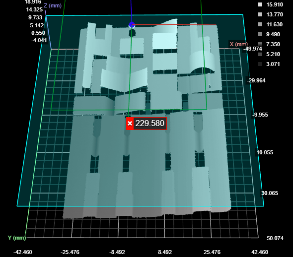
Transformed data
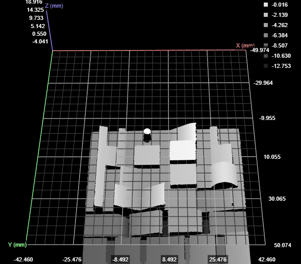
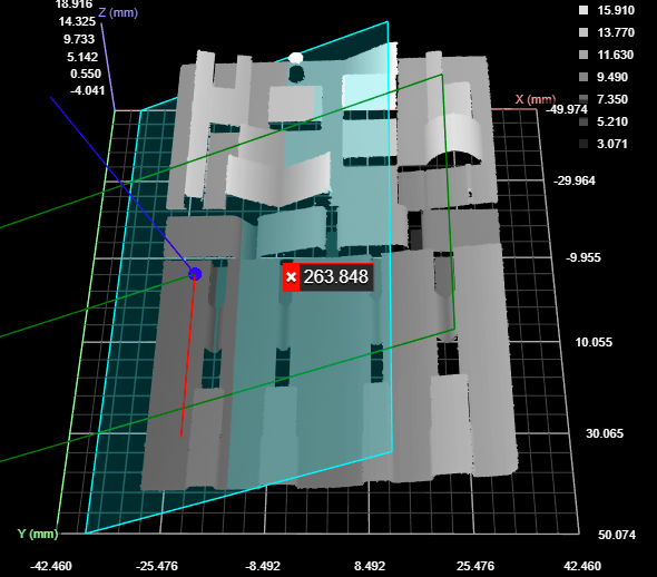
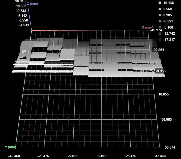
Plane + Line
| New Z=0 XY Plane | New X Axis | New Origin |
|---|---|---|
| Matches the input plane. | Line projected onto the plane. | Old origin projected onto the projected line. |
Original data with overlay
Transformed data
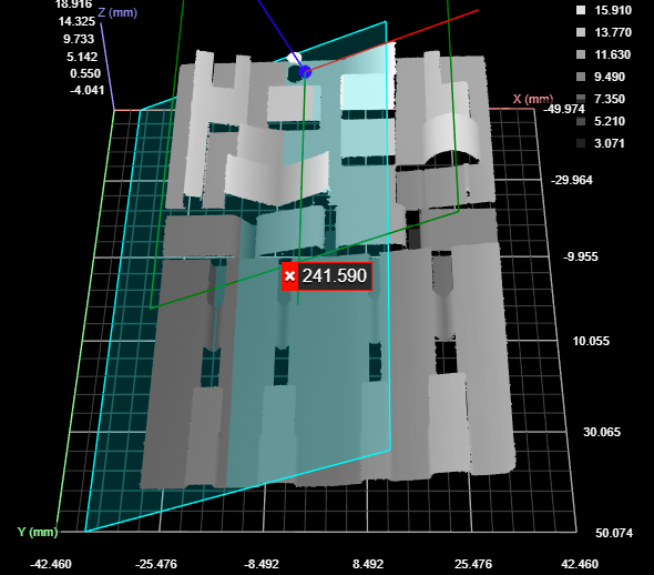
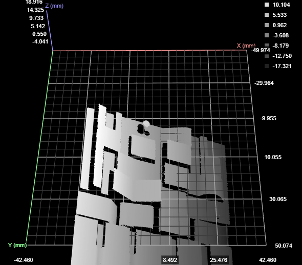
Plane + Point
| New Z=0 XY Plane | New X Axis | New Origin |
|---|---|---|
| Matches the input plane. | Parallel to the old X axis. | At the input point, projected onto the plane. |
Original data with overlay
Transformed data
Line + Point
| New Z=0 XY Plane | New X Axis | New Origin |
|---|---|---|
| The new plane contains the line. The intersection of the new plane and the old plane is perpendicular to the input line. | Matches the line. | The input point projected onto the line. |
Original data with overlay
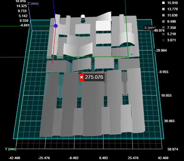
Transformed data
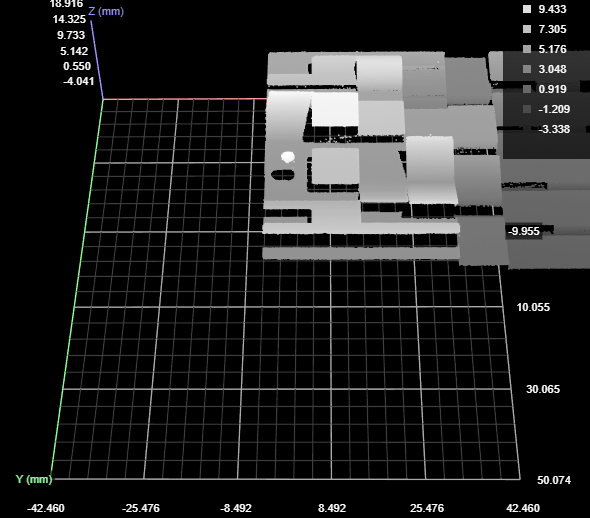
Plane + Line + Point
| New Z=0 XY Plane | New X Axis | New Origin |
|---|---|---|
| Matches the input plane. | The input line projected onto the plane. | The input point projected onto the input line. |
Original data with overlay
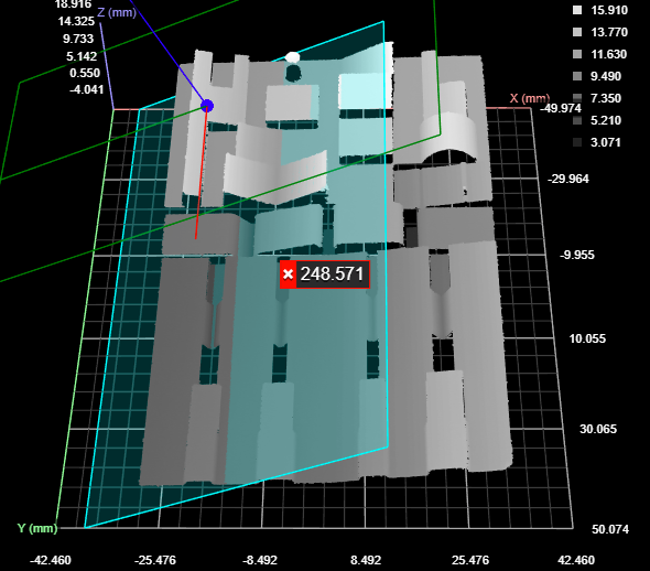
Transformed data
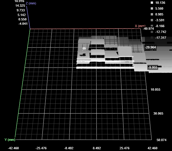
For information on adding, managing, and removing tools and measurements, as well as detailed descriptions of settings common to most tools, see Tools Panel.
Scaling Modes
Line profile sensors have independent X and Y resolution settings: the former is set using the Spacing setting (for more information, see Spacing), whereas the Y resolution is set using the Spacing Interval setting in the Trigger panel (for more information, see Trigger Settings). In many applications, the X resolution can be as much as 3-5 times higher than the Y resolution. Rotating scan data around Z greater than 45 degrees (for example, with the Transform tool) when there is a large difference between X and Y resolutions can result in significant data quality reduction. To avoid data quality reduction, choose one of the scaling modes that the tool offers (see below).
Measurements, Data, and Settings
| Measurement |
|---|
|
Running Time (ms) The amount of time required for tool execution. Used for diagnostic purposes. |
| Type | Description |
|---|---|
|
Transformed Surface |
The transformed surface. Available via the Stream drop-down in other tools. |
| Parameter | Description |
|---|---|
|
Source |
The sensor |
|
Input Plane |
The plane the tool uses to transform the surface scan data. |
|
Input Line |
The line the tool uses to transform the surface scan data. |
|
Input Point |
The point the tool uses to transform the surface scan data. |
|
Scaling Mode |
Determines whether the tool scales the X or Y resolution so that they are the same (a 1:1 ratio), or leaves the X and Y resolutions as the original. One of the following.
For more information, see Scaling Modes. |
|
Add Fixed Transform |
When enabled, displays X, Y, and Z offset and angle fields you can use to set additional transformations, which are applied after any transformations supplied by the input geometric features. Setting a fixed transformation can be useful if the geometric features the tool uses results in data rotated to an unusual orientation; you could, for example, rotate the data 90 or 180 degrees so that it is in the "expected" orientation, or shift it so that it's easier to work with. |
|
Use Region |
When this setting is enabled, the tool only outputs the surface contained in the defined region. |
|
Filters |
The filters that are applied to measurement values before they are output. For more information, see Filters. |
|
Decision |
The Max and Min settings define the range that determines whether the measurement tool sends a pass or fail decision to the output. For more information, see Decisions. |
| Anchor | Description |
|---|---|
|
X |
Lets you choose the X |

|
A measurement must be enabled in the other tool for it to be available as an anchor. The anchor measurement should also be properly configured before using it as an anchor. |

|
For more information on anchoring, see Measurement Anchoring. |
