Measurement Anchoring
When parts that a sensor is scanning move on a transport mechanism such as a conveyor, their position typically changes from part to part in one or both of the following ways:
- along the X, Y, and Z axes (basically, horizontally and vertically)
- around the Z axis (orientation angle)
When the position and angle variation between parts is minor—for example, when scanning electronic parts in trays—you can anchor one tool to one or more measurements from another tool to compensate for these minor shifts. As a result, Gocator can correctly place the anchored tool's measurement regions on each part. This increases the repeatability and accuracy of measurements.

|
For cases where movement from part to part is more drastic, you can use part matching to compensate. However, in order for part matching to work properly, the entire part typically must be visible in the field of view. |
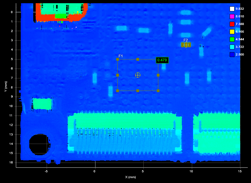
For example, the following image shows a surface scan of a PCB. A Surface Dimension height measurement returns the height of a surface-mount capacitor relative to a nearby surface (the F1 region).
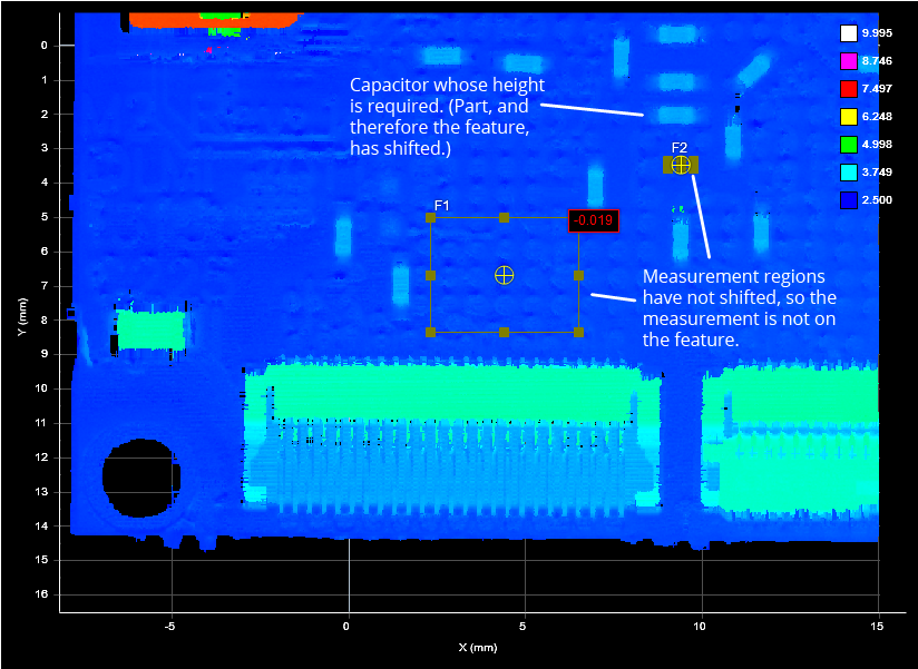
In the following scan, the part has shifted, but the measurement regions remain where they were originally configured, in relation to the sensor or system coordinate system, so the measurement returned is incorrect:
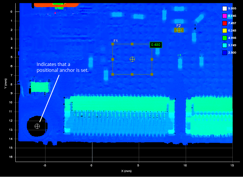
When you set a tool's anchor source, an offset is calculated between the anchored tool and the anchor source. This offset is used for each frame of scanned data: the anchored tool's measurement region is placed in relation to the anchor source, at the calculated offset.
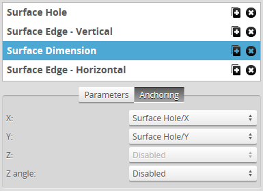
In the following image, after the Surface Dimension tool is anchored to the X and Y measurements from a Surface Hole tool (placed over the hole to the lower left), Gocator compensates for the shift—mostly along the Y axis in this case—and returns a correct measurement, despite the shift.
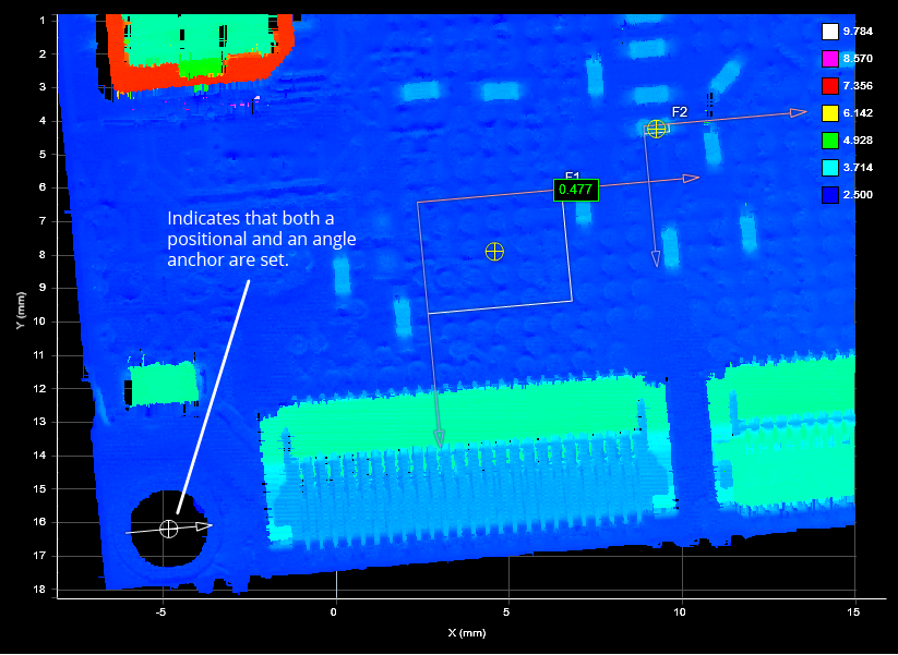
You can combine the positional anchors (X, Y, or Z measurements) with an angle anchor (a Z Angle measurement) for optimum measurement placement. For example, in the following scan, the part has not only shifted on the XY plane but also rotated around the Z axis. Anchoring the Surface Dimension tool to the Z Angle measurement of a Surface Edge tool (placed on the lower edge in this case) compensates for the rotation, and the anchored tool returns a correct measurement.
|
|
If Z Angle anchoring is used with both X and Y anchoring, the X and Y anchors should come from the same tool. |
|
|
If Z Angle anchoring is used without X or Y anchoring, the tool's measurement region rotates around its center. If only one of X or Y is used ,the region is rotated around its center and then shifted by the X or Y offset. |
Several anchors can be created to run in parallel. For example, you could anchor the measurements of one tool relative to the left edge of a target, and anchor the measurements of another tool relative to the right edge of a target.
You can combine positional anchors (X, Y, or Z) with angle anchors (Z Angle) for optimum measurement placement.
To anchor a
In Profile mode
In Surface mode
|
|||||
A suitable tool is one that returns an X, Y, or Z position |
|||||
You can adjust the measurement region graphically in the data viewer or manually by expanding the Regions area. The position and size of the anchoring tool’s measurement regions define the zone within which movement will be tracked.
See Feature Points for more information on feature types. |
|||||
Any tool can be anchored. |
|||||
|
|||||
|
|||||
If the sensor is running, the anchored tool’s measurement regions are shown in white to indicate the regions are locked to the anchor. The measurement regions of anchored tools cannot be adjusted. The anchored tool’s measurement regions are now tracked and will move with the target’s position |
|||||
|
To remove an anchor from a tool:
Select Disabled in the X, Y, or Z drop-down. |