Intersect
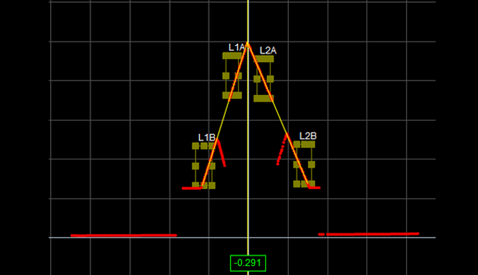
The Intersect tool determines intersect points and angles.
The Intersect tool's measurements require two fit lines, one of which is a reference line set to the X axis (z = 0), the Z axis (x = 0), or a user-defined line.
|
|
|
For information on adding, managing, and removing tools and measurements, as well as detailed descriptions of settings common to most tools, see Tools Panel.
Measurements, Features, and Settings
| Measurement | Illustration |
|---|---|
|
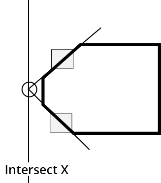
X Finds the intersection between two fitted lines and measures the X axis position of the intersection point. |
|
|
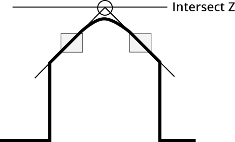
Z Finds the intersection between two fitted lines and measures the Z axis position of the intersection point. |
|
|
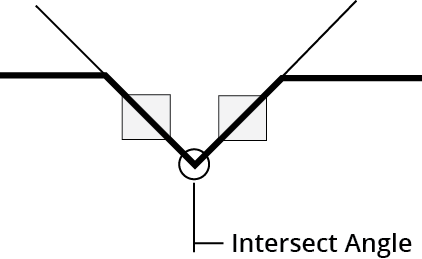
Angle Finds the angle subtended by two fitted lines. |
|
| Type | Description |
|---|---|
| Intersect Point |
The point of intersection. |
| Line |
The intersect line. |
| Base Line |
The base line. |

|
For more information on geometric features, see Geometric Features. |
| Parameter | Description |
|---|---|
|
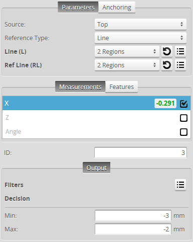
Source |
The sensor |
|
Stream |
The data that the tool will apply measurements to. This setting is only displayed when data from another tool is available as input for this tool. |
|
Reference Type |
Determines the type of the reference line. X-Axis: The reference line is set to the X axis. Z-Axis: The reference line is set to the Z axis Line: The reference line is defined manually using the Ref Line parameter. One or two regions can be used to define the line. |
|
Line |
You can use one or two fit areas for the fit line. To set the region (or regions) of the fit line, adjust it graphically in the data viewer, or expand the feature using the expand button ( For more information on fit lines, see Fit Lines. |
|
Ref Line |
Used to define the reference line when Line is selected in the Reference Type parameter. To set the region (or regions) of the reference line, adjust it graphically in the data viewer, or expand the feature using the expand button ( For more information on fit lines, see Fit Lines. |
|
Angle Range (Angle measurement only) |
Determines the angle range. The options are: -90 – 90 0 – 180 |
|
Filters |
The filters that are applied to measurement values before they are output. For more information, see Filters. |
|
Decision |
The Max and Min settings define the range that determines whether the measurement tool sends a pass or fail decision to the output. For more information, see Decisions. |
 ) and enter the values in the fields. For more information on regions, see
 | Anchor | Description |
|---|---|
|
X or Z |
Lets you choose the X or Z measurement of another tool to use as a positional anchor for this tool. |
|
|
A measurement must be enabled in the other tool for it to be available as an anchor. The anchor measurement should also be properly configured before using it as an anchor. |
|
|
For more information on anchoring, see Measurement Anchoring. |