Regions
Many measurement tools use user-defined regions to limit the area in which measurements occur

|
You can disable regions and force a tool to use the entire active area by unchecking the checkbox next to the Regions setting. |
All tools provide region settings under the upper, tool-level Parameters tab. This region applies to all of a tool's measurements. Region settings are sometimes found within expandable feature sections in a tool's panel.
Some of LMI's more recent tools provide "flexible" regions, which in addition to rectangular regions let you create circular and elliptical regions (which can optionally be annular) and polygon regions. These tools also let you use Surface and Surface Intensity data as masks. As of this writing, the following tools have flexible regions:
- Surface Direction Filter
- Surface Filter
- Surface Flatness
- Surface Mask
- Surface OCR
- Surface Segmentation
Other tools are currently limited to rectangular regions. However, you can get "flexible regions" in a tool that doesn't directly support them by using the Surface Mask tool, and using that tool's output as the other tool's input. For more information, see Mask.
For information on setting "flexible" regions, see Flexible Regions.
|
|
In 2D mode, the tool region defaults to the center of the current data view, not the global field of view. In 3D mode, the region defaults to the global field of view. Use the region reset button ( |
 ) to set the size of a region to its default. This is useful after zooming in or out in the data viewer.
Standard Regions
The standard regions are limited to rectangles or boxes.
To configure standard regions:
|
|||||
|
|||||
You can also configure regions manually by clicking the expand button ( |
 ) and entering values in the fields. This is useful if you need to set precise values.
Flexible Regions
The following parameters are available in tools that support flexible regions
| Parameter | Description |
|---|---|
|
Number of Regions |
The number of regions the tool uses to extract surface data. You can define up to 15 or 16 regions. This parameter is not available in some tools. When you specify more than one region, the regions are initially stacked on top of one another, in the same location. |
|
Mask Type {n} Region Type {n} |
For each mask (in the Surface Mask tool) or region, the type. Regions can overlap. One of the following. (For more information on the settings you use with the Circle and Ellipse types, see Working with Circular and Elliptical Regions.
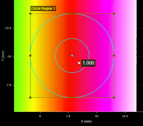
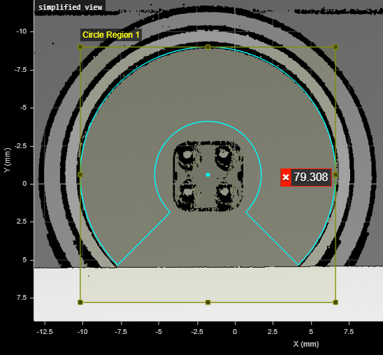
Circle Extracts a circular region from the surface data, constrained by a square region. Set the region's inner circle (inner cyan circle below) using the Inner Circle Diameter parameter to extract annular data. Use the Sector Start Angle and Sector Angle Range settings to extract a partial circular or elliptical region.
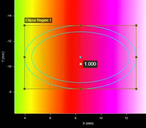
Ellipse Extracts an elliptical region from the surface data, constrained by a square or rectangular region. Set the region's inner ellipse (inner cyan ellipse below) using the Inner Ellipse Major Axis and Inner Ellipse Minor Axis parameters to extract annular data. Use the Sector Start Angle and Sector Angle Range settings to extract a partial circular or elliptical region.
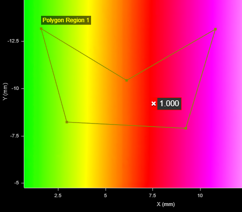
Polygon Extracts a polygonal region with the number of vertices specified in Vertex Count. You can define the shape of the polygon using a mouse in the data viewer, dragging and dropping the vertex points.
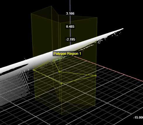
Note that you can't adjust the height of a polygon region: it occupies the entire vertical space available:
Rectangle Extracts a rectangular region from the surface data.
Surface Uses the Surface data you select in Mask Source to create a mask. Surface Intensity Uses the intensity data you select in Mask Source to create a mask. Set the Low Threshold and High Threshold parameters as required. |
|
Inner Circle Diameter |
Only available when Region Type {n} is set to Circle. Defines the diameter of the inner circle. Set this parameter to a value greater than 0 to extract a ring of data. Set this parameter to 0 to extract a circle of data. |
|
Inner Ellipse Major Axis Inner Ellipse Minor Axis |
Only available when Region Type {n} is set to Ellipse. These parameters define the major and minor axes of the inner ellipse, respectively Set this parameter to a value greater than 0 to extract a ring of data. Set this parameter to 0 to extract an elliptical disk of data. |
|
Sector Start Angle Sector Angle Range |
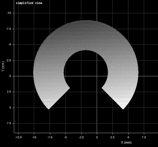
Only available when Region Type {n} is set to Circle or Ellipse Use these parameters together to extract a partial ring of data. Sector Start Angle controls the starting angle of the data, whereas Sector Angle Range controls the length of the arc. Note that the angles and ranges in these parameters are measured clockwise around Z, where 0 degrees is along the positive X axis. For example, in the first image below, Sector Start Angle is set to 135, and Sector Angle Range is set to 270. The resulting extracted partial ring (or annular data) is shown below that.
For more information on how these settings work together, see Working with Circular and Elliptical Regions. |
|
Mask Source |
Only available when Region Type {n} is set to Surface or Surface Intensity. The Surface or Surface Intensity data the tool uses to create a mask. |
|
Low Threshold High Threshold |
Only available when Region Type {n} is set to Surface Intensity. The low and high thresholds the tool uses in combination with the intensity mask. |

Working with Circular and Elliptical Regions
When you set a region's type to Circle or Ellipse, the tool displays several additional settings that work together to define the region. Sector Start Angle and Sector Angle Range work together to define the start and end of a partial circular/elliptical region (solid or annular). A region will be annular if Inner Circle Diameter is non-zero. Note that the "length" of the partial region extends from the start angle. In the following illustration, the start angle (θ) is 135 degrees relative to the 0-degree point indicated below, and the region extends 270 degrees (δ) from that, clockwise around Z.

Sector Start Angle starts at the 0-degree point around Z.
Note that the angles defining a partial circular/elliptical region are relative to the region, and not the sensor's coordinate system. So a region rotated 30 degrees using its Z Angle setting rotates the start angle and angle range by 30 degrees.
When you set a region type to Ellipse, instead of the inner circle diameter, you must set the major and minor axes of the inner ellipse.

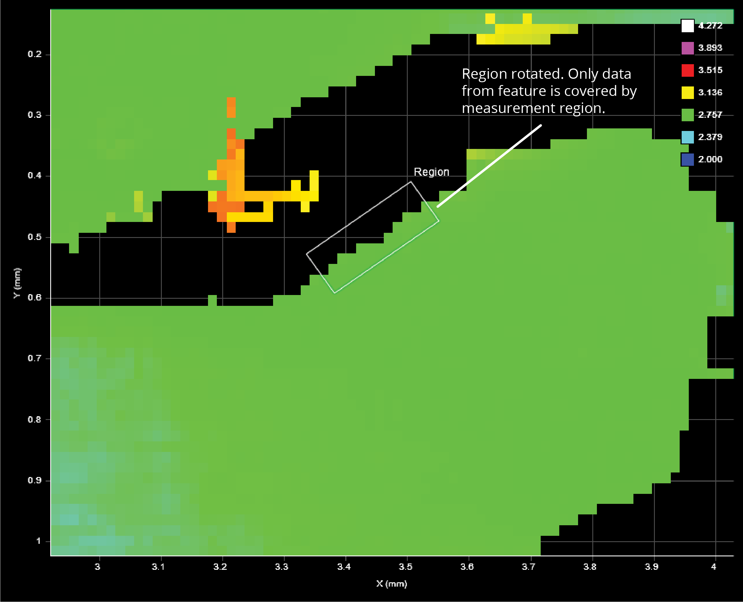
Region Rotation
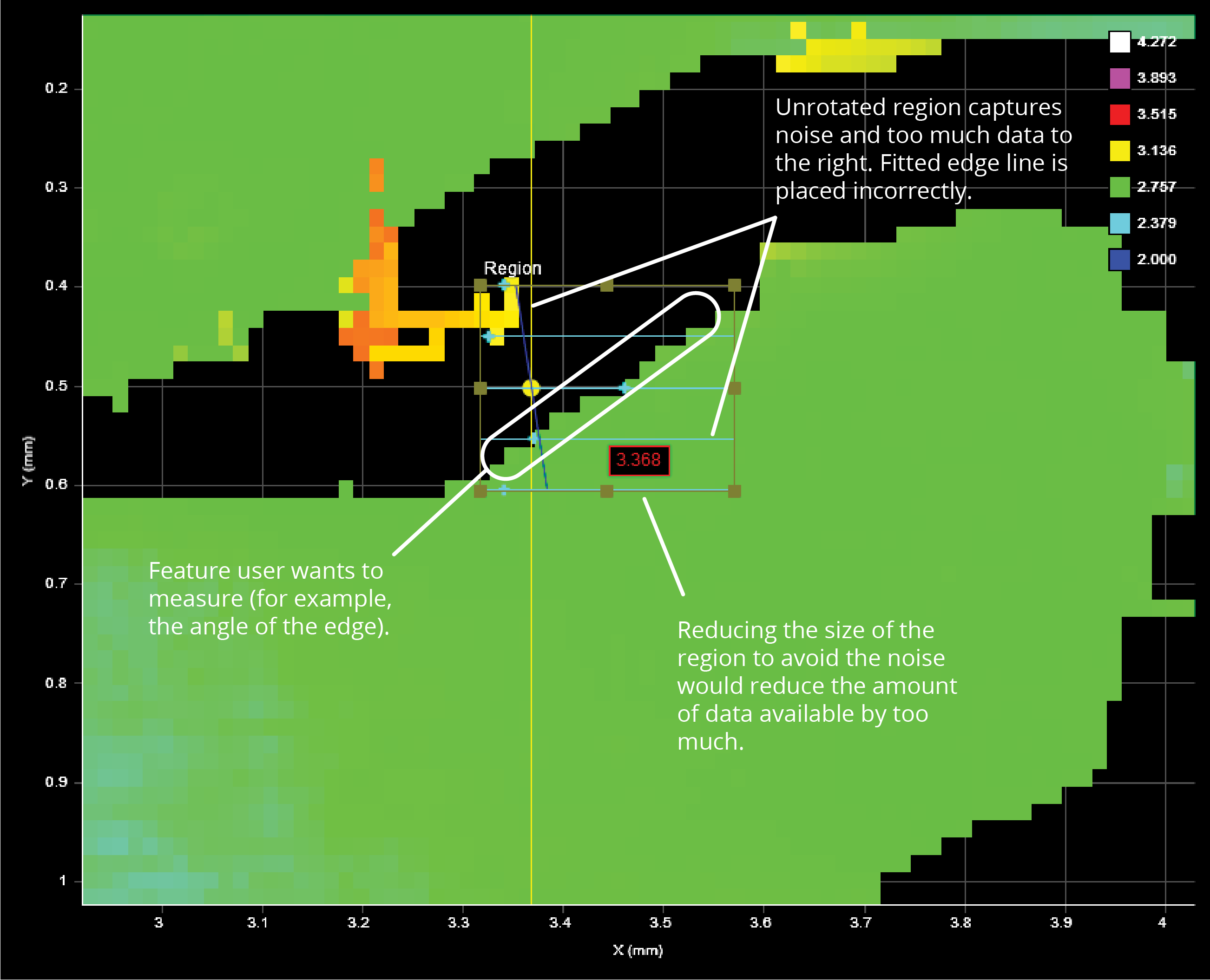
The measurement region of some tools can be rotated by setting the region's Z Angle to better accommodate features that are on an angle on a target. By rotating the measurement region, data not related to the feature can often be excluded, improving accuracy of measurements.
To rotate measurement regions:
| 1. | Determine the length and width of the region that will be required once it is rotated. |
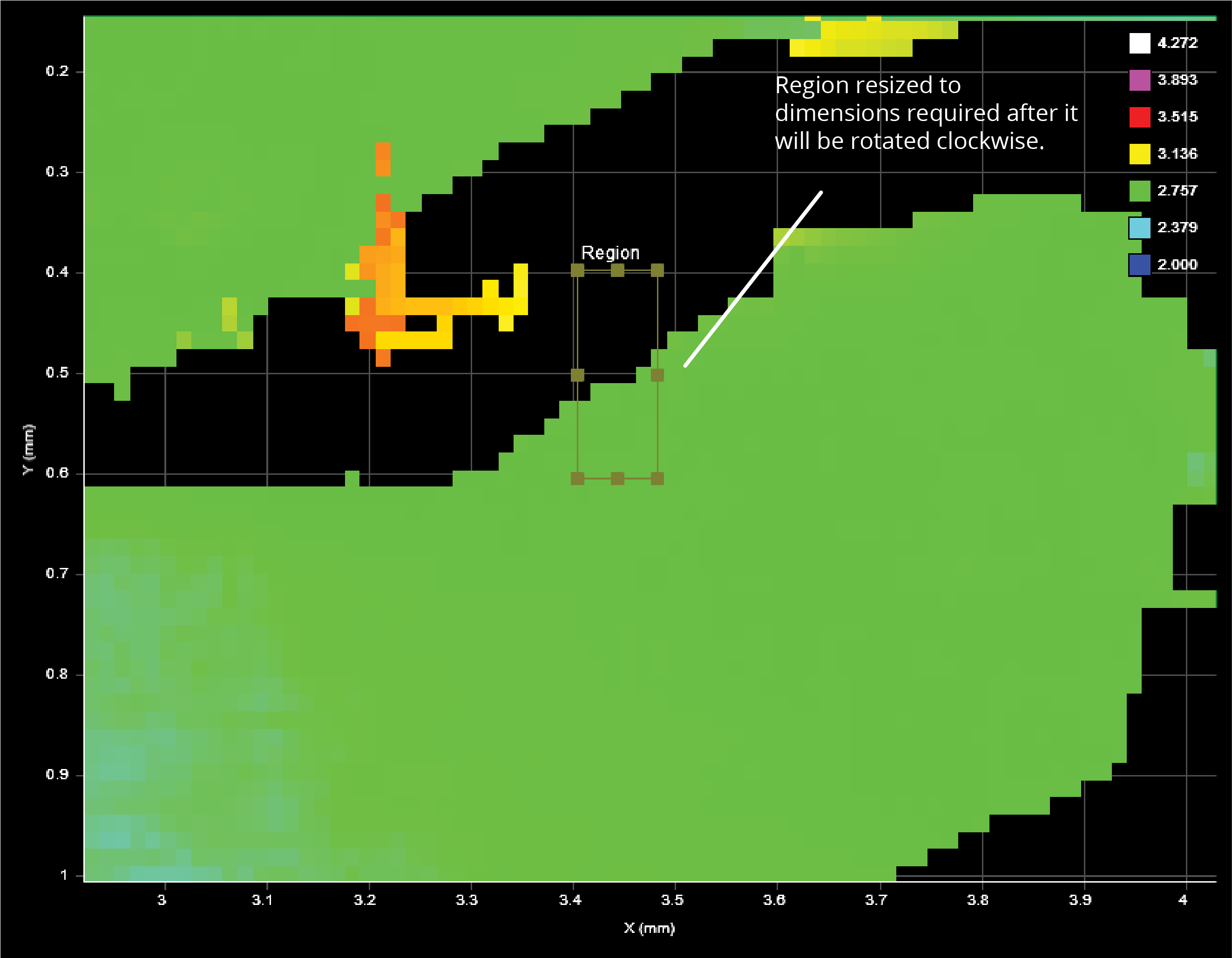
| 2. | Expand the Region setting and then set a value in Z Angle. |
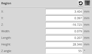
The region rotates clockwise around the Z axis relative to the X axis.
Once the region has been rotated, you can modify its size and location in the data viewer using the mouse. You can also modify its dimensions and its location manually by changing the region's values in the Region setting.
|
|
Some tools let you disable regions entirely and force the measurement tool to use the entire active area by unchecking the checkbox next to the Regions setting. |