Panel
The Panel tool provides Gap and Flush measurements.
|
|
|
The Panel tool uses a complex feature-locating algorithm to find the gap or calculate flushness and return measurements. The behavior of the algorithm can be adjusted by changing the parameters in the measurement panel. See "Gap and Flush Algorithm" in the Gocator Measurement Tool Technical Manual for a detailed explanation of the algorithm.

|
You must make sure that there are enough data points to define the edge in the profile, by properly settng up exposure, etc. If not, the algorithm will not function. |
For information on adding, managing, and removing tools and measurements, as well as detailed descriptions of settings common to most tools, see Tools Panel.
| Measurement | Illustration |
|---|---|
|
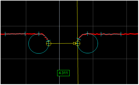
Gap Measures the distance between two surfaces. The surface edges can be curved or sharp. |
|
|
Flush Measures the flushness between two surfaces. The surface edges can be curved or sharp. |
|
|
Left Gap X Returns the X position of the edge feature on the left side used to measure the gap. |
|
|
Left Gap Z Returns the Z position of the edge feature on the left side used to measure the gap. |
|
|
Left Flush X Returns the X position of the feature on the left side used to measure flushness. |
|
|
Left Flush Z Returns the Z position of the feature on the left side used to measure flushness. |
|
|
Left Surface Angle The angle of the left side surface relative to the X axis. |
|
|
Right Gap X Returns the X position of the edge feature on the right side used to measure the gap. |
|
|
Right Gap Z Returns the Z position of the edge feature on the right side used to measure the gap. |
|
|
Right Flush X Returns the X position of the feature on the right side used to measure flushness. |
|
|
Right Flush Z Returns the Z position of the feature on the right side used to measure flushness. |
|
|
Right Surface Angle The angle of the right side surface relative to the X axis. |


| Parameter | Description |
|---|---|
|
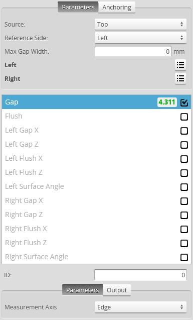
Source |
The sensor |
|
Stream |
The data that the tool will apply measurements to. This setting is only displayed when data from another tool is available as input for this tool. |
|
Reference |
Defines the side used to calculate the |
|
Max Gap Width |
The maximum width of the gap. Allows the tool to filter gaps greater than the expected width. This can be used to single out the correct gap when there are multiple gaps in the field of view. |
|
Measurement Axis Gap measurement only |
Defines the direction that the gap is calculated, in relation to the reference side (see above). Surface: In the direction of the fitted surface line of the reference surface. Edge: In the direction perpendicular to the edge of the reference surface. Distance: The Cartesian distance between the two feature locations. |
|
Absolute Flush measurement only |
When enabled, returns an absolute value rather than a signed value. |
|
Filters |
The filters that are applied to measurement values before they are output. For more information, see Filters. |
|
Decision |
The Max and Min settings define the range that determines whether the measurement tool sends a pass or fail decision to the output. For more information, see Decisions. |
| Parameter | Description |
|---|---|
|
Max Void Width |
The maximum allowed width of missing data caused by occlusion or data dropout. |
|
Min Depth |
Defines the minimum depth before an opening could be considered to have a potential edge. The depth is the perpendicular distance from the fitted surface line. |
|
Surface Width |
The width of the surface area in which data is used to form the fitted surface line. This value should be as large as the surface allows. |
|
Surface Offset |
The distance between the edge region and the surface region. Setting a small value allows the edge within a tighter region to be detected. However, the measurement repeatability could be affected if the data from the edge are considered as part of the surface region (or vice versa). A rule of thumb is to set Surface Offset equal to Nominal Radius. |
| Nominal Radius |
The radius of the curve edge that the tool uses to locate the edge region. |
| Edge Angle |
A point on the best fit circle to be used to calculate the feature point. The selected point is on the circumference at the specified angle from the start of the edge region. The angle is measured from the axis perpendicular to the fitted surface line. |
| Edge Type |
Defines the type of feature point to use for the edge (Corner or Tangent). A tangent edge point is the point selected based on the defined Edge Angle. A corner edge point is the intersect point between the fitted surface line and a edge line formed by interpolating the points at and after the tangent within the edge region. |
|
Region |
The region to which the tool's measurements will apply. For more information, see Regions. |
| Anchor | Description |
|---|---|
|
X or Z |
Lets you choose the X or Z measurement of another tool to use as a positional anchor for this tool. |
|
|
A measurement must be enabled in the other tool for it to be available as an anchor. The anchor measurement should also be properly configured before using it as an anchor. |
|
|
For more information on anchoring, see Measurement Anchoring. |