Part Detection
In Surface mode, a sensor can analyze scan data to identify discrete objects.
Part detection must be manually enabled when Type is set to Fixed Length, Variable Length, or Rotational in the Surface Generation panel. When Type is set to Continuous, part detection is always enabled.
Part detection can be performed when Source in the Trigger panel is set to Time or Encoder. To use the Time trigger source, the travel speed must be calibrated. To use the Encoder trigger source, the encoder resolution must be calibrated. See Aligning Sensors for more information.
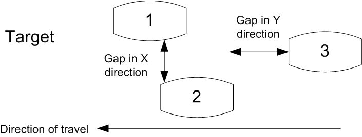
Multiple parts
You can use part detection as a trigger event for digital output to use the sensor like a photo-eye, eliminating the cost of installing a separate photo-eye. For more information, see To respond to a part detection.

|
Gocator also lets you isolate and then measure using one of two Surface measurement tools (for more information on these tools, see Blob and Segmentation). For a comparison of part detection and these tools, see Isolating Parts from Surface Data. |
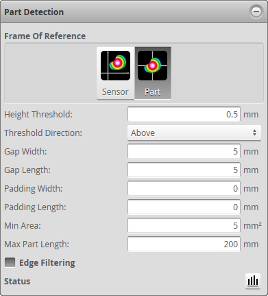
The following settings can be tuned to improve the accuracy and reliability of part detection.
| Setting | Description |
|---|---|
|
Height Threshold |
Determines the In an Opposite layout, the threshold is applied to the difference between the top and the bottom profile. A target thinner than the threshold value is ignored, including places where only one of either top or bottom is detected. To separate parts by gated external input, set the Height Threshold to the active area Z offset (i.e., minimum Z position of the current active area), set Source to Time or Encoder and check the Gate on External Input checkbox in the |
|
Include one-sided data |
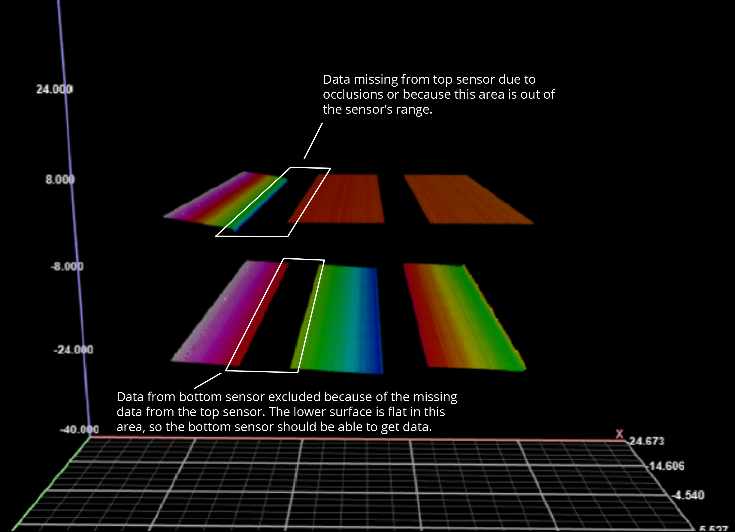
The option is only displayed with dual-sensor systems in Opposite layout, or multi-sensor systems in Grid layout with at least one sensor in the Bottom row. When the option is disabled, data points from a sensor are excluded if the points directly opposite from the other sensor are missing (due to occlusions, drop-outs, and so on). When the option is enabled, data points are included even if data points from the other sensor are missing. The following image shows surface data from a dual-sensor system in which the sensors are mounted facing each other. In this case, Include one-sided data is disabled.
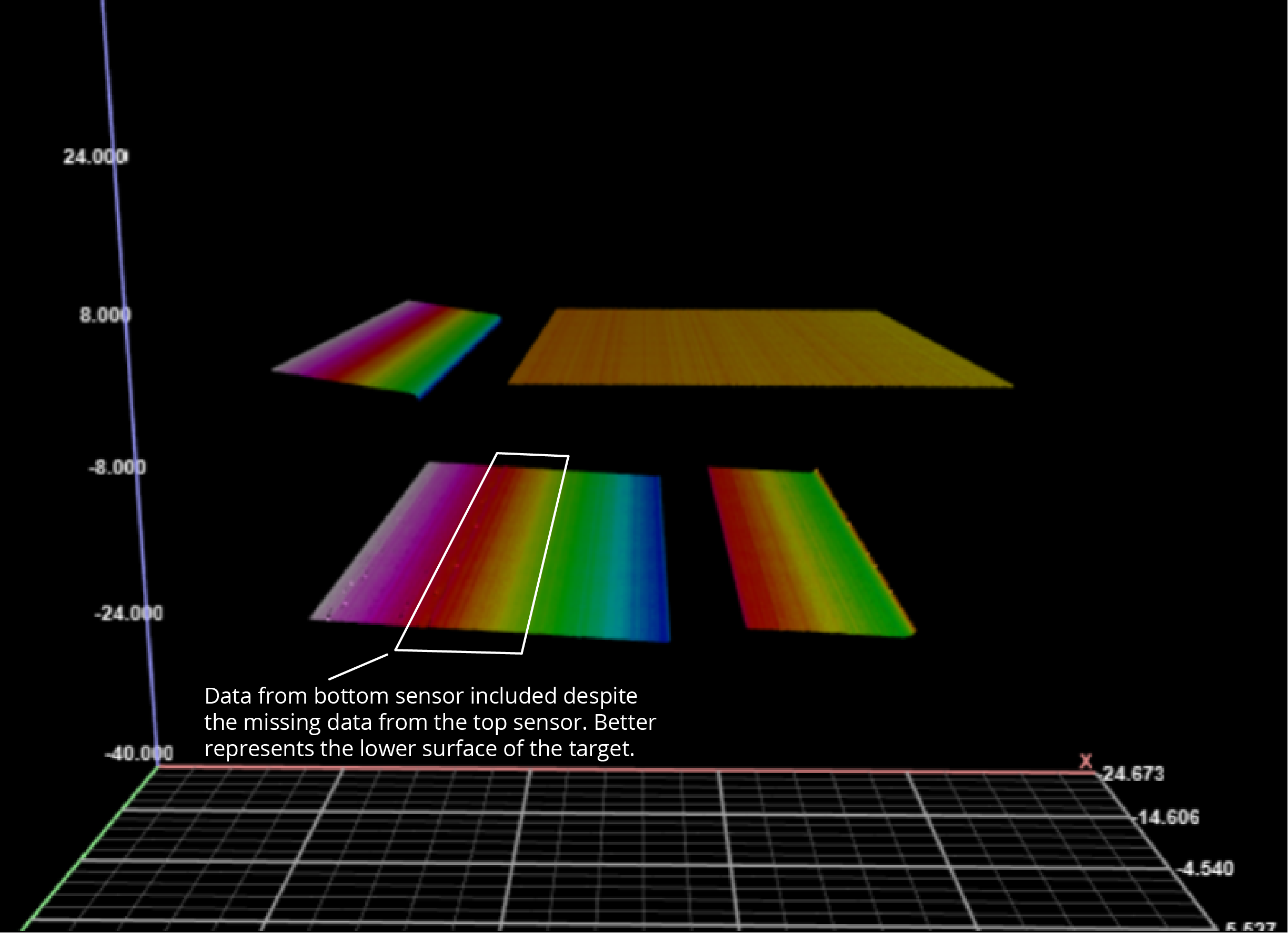
The data on the upper left is missing, due to the shape of the target: getting data from this area is difficult or impossible, due to occlusions or simply because this part of the upper surface is beyond the top sensor's measurement range. Data is missing on the left of the lower surface, even though the target is flat in this area. In the following image, Include one-sided data is enabled. The result is that data from the lower left is included in the scan data, better representing the actual target. (The same situation is occurring on the right side of the surfaces.)
In general, you should leave this setting enabled. |
|
Threshold Direction |
Determines if parts should be detected above or below the height threshold. |
|
Gap Width
|
Determines the minimum separation between objects on the X axis. If parts are closer than the gap interval, they will be merged into a single part. |
| Gap Length |
Determines the minimum separation between objects on the Y axis. If parts are closer than the gap interval, they will be merged into a single part. |
|
Padding Width Padding Length |
|
|
Min Area |
Determines the minimum area for a detected part. Set this value to a reasonable minimum in order to filter out small objects or noise. |
|
Max Part Length |
Determines the maximum length of the part object. When the object exceeds the maximum length, it is automatically separated into two parts. |
|
Frame of Reference |
Determines the coordinate reference for surface measurements.
Sensor When Frame of Reference is set to Sensor, the sensor's frame of reference is used.
The Surface Bounding Box GlobalX and GlobalY measurements (see Bounding Box) are exceptions: regardless of the Frame of Reference setting, these measurements produce the Sensor frame of reference values of the Part frame of reference origin (which is the bounding box center), except for GlobalY when parts are segmented from continuous surfaces. In this case the GlobalY value is the Y value relative to the encoder zero position. These values can be used to locate Part frame of reference measurements in a world space.
Part When Frame of Reference is set to Part, all measurements |
|
Status |
Provides details on the status of the part detection engine. For more information, see Part Detection Status. |
|
Edge Filtering |
To set up part detection:
If this mode is not selected, you will not be able to configure part detection. |
||||||
When Surface Generation is set to Continuous, part detection is always enabled. |
||||||
See the part detection parameters above for more information. |
 button.