Countersunk Hole
The Countersunk Hole tool locates a countersunk circular opening within a region of interest on the surface and provides measurements to evaluate characteristics of countersunk holes, including the position (X, Y, and Z) of the center of the hole, outside radius of the hole, hole bevel angle, and the depth of the hole. The countersunk hole can be on a surface at an angle to the sensor. The tool also supports measuring holes drilled at an angle relative to the surrounding surface.

|
The tool does not search for or detect the feature. The tool expects that the feature, conforming reasonably well to the defined parameters, is present and that it is on a sufficiently uniform background. |
|
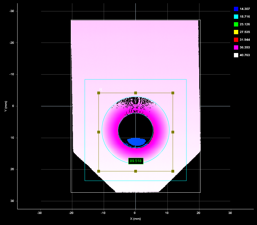
2D View |
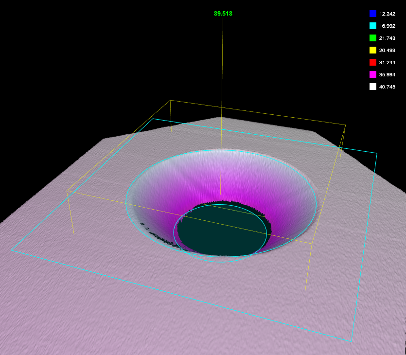
3D View |
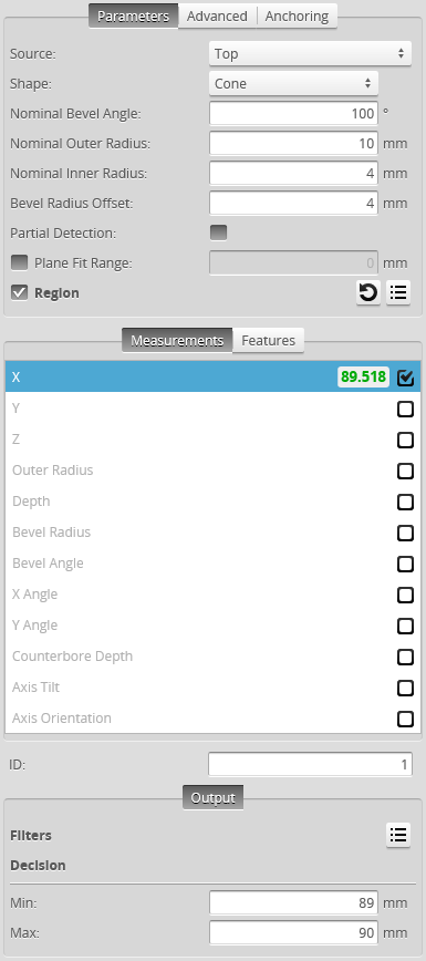
Measurement Panel
For information on adding, managing, and removing tools and measurements, as well as detailed descriptions of settings common to most tools, see Tools Panel.
Measurements, Features, and Settings
| Measurement | Illustration | ||
|---|---|---|---|
|
X Determines the X position of the center of the countersunk hole. |
|
||
|
Y Determines the Y position of the center of the countersunk hole. |
|||
|
Z Determines the Z position of the center of the countersunk hole. |
|||
|
Outer Radius Determines the outer radius of the countersunk hole. When a hole is cut at an angle relative to the surrounding surface, the outer radius is calculated as if the hole were not cut at an angle.
|
|
||
|
Depth Determines the depth of the countersunk hole relative to the surface that the countersunk hole is on. |
|
||
|
Bevel Radius Determines the radius at a user-defined offset (Offset setting) relative to the surface that the countersunk hole is on.
|
|
||
|
Bevel Angle Determines the angle of the hole's bevel. |
Cone
Counterbore |
||
|
X Angle Determines the angle the hole relative to the X axis. |
Cone
Counterbore |
||
|
Y Angle Determines the angle of the hole relative to the Y axis. |
|||
| Counterbore Depth
Determines the depth of a counterbore. |
|
||
| Axis Tilt
Measures the tilt of the axis of the hole relative to the surface surrounding the hole.
|
|
||
| Axis Orientation
Measures the angle of the axis of the hole around the normal of the surface surrounding the hole, relative to the X axis.
|
|


| Type | Description |
|---|---|
| Center Point |
The center point of the countersunk hole. The Z position of the center point is at the Z position of the surrounding surface. |
|
|
For more information on geometric features, see Geometric Features. |
| Parameter | Description |
|---|---|
|
Source |
The sensor |
|
Shape |
The shape of the countersunk hole. (See illustrations above.) 0 – Cone 1 – Counterbore |
|
Nominal Bevel Angle |
The expected bevel angle of the countersunk hole. |
|
Nominal Outer Radius |
The expected outer radius of the countersunk hole. |
|
Nominal Inner Radius |
The expected inner radius of the countersunk hole. |
|
Bevel Radius Offset |
The offset, relative to the surface that the countersunk hole is on, at which the bevel radius will be measured. |
|
Partial Detection |
Enable if only part of the hole is within the measurement region. If disabled, the hole must be completely in the region of interest for results to be valid. |
|
Plane Fit Range |
Excludes data beyond the specified distance from the plane surrounding the hole. You can use this setting to exclude surfaces close to the countersunk hole that step down from the plane surrounding the hole that could make measurement of the hole less reliable. |
|
Region |
The region to which the tool's measurements will apply. For more information, see Regions. |
|
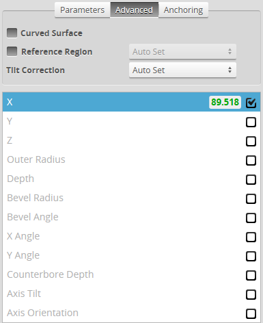
Curved Surface |
Whether the surface that the countersunk hole is on is curved. When this setting is enabled, specify the orientation of the curvature in degrees in the Curve Orientation setting. |
|
Curve Orientation |
The orientation of the curvature in degrees. Only visible when Curved Surface is enabled. |
|
Reference Regions |
The tool uses the reference regions to calculate the Z position of the hole. It is typically used in cases where the surface around the hole is not flat.
When this option is set to Autoset, the algorithm automatically determines the reference region. When the option is not set to Autoset, you must manually specify one or two reference regions. The location of the reference region is relative to the detected center of the hole and positioned on the nominal surface plane. When Reference Region is disabled, the tool measures the hole's Z position using all the data in the measurement region, except for a bounding rectangular region around the hole. |
|
Tilt Correction |
Tilt of the target with respect to the alignment plane. Autoset: The tool automatically detects the tilt. The measurement region to cover more areas on the surface plane than other planes. Custom: You must enter the X and Y angles manually in the X Angle and Y Angle parameters (see below). |
|
X Angle Y Angle |
The X and Y angles you must specify when Tilt Correction is set to Custom. You can use the Surface Plane tool's X Angle and Y Angle measurements to get the angle of the surrounding surface, and then copy those measurement's values to the X Angle and Y Angle parameters of this tool. |
|
Filters |
The filters that are applied to measurement values before they are output. For more information, see Filters. |
|
Decision |
The Max and Min settings define the range that determines whether the measurement tool sends a pass or fail decision to the output. For more information, see Decisions. |

| Anchor | Description |
|---|---|
|
X |
Lets you choose the X |
|
|
A measurement must be enabled in the other tool for it to be available as an anchor. The anchor measurement should also be properly configured before using it as an anchor. |
|
|
For more information on anchoring, see Measurement Anchoring. |