Opening
|
The Opening tool locates rounded, rectangular, and rounded corner openings. The opening can be on a surface at an angle to the sensor.
The tool uses a complex feature-locating algorithm to find a hold and then return measurements. See "Opening Algorithm" in the Gocator Measurement Tool Technical Manual for a detailed explanation of the algorithm. The behavior of the algorithm can be adjusted by changing the parameters in the measurement panel. |
|
||
|
The algorithm can separate out background information that appears inside the opening. It can also detect a slot that only partially appears in the data. |
|
||
|
The shape of the opening is defined by its type and its nominal width, length, and radius. The orientation defines the rotation around the normal of the alignment plane. |
|


|
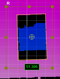
2D View |
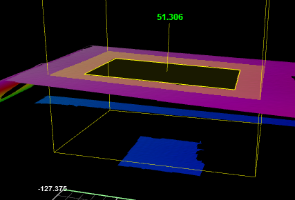
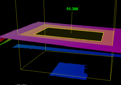
3D View |
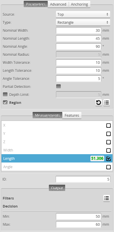
Measurement Panel
For information on adding, managing, and removing tools and measurements, as well as detailed descriptions of settings common to most tools, see Tools Panel.
Measurements, Features, and Settings
| Measurement | Illustration |
|---|---|
|
X Determines the X position of the opening's center. |
|
|
Y Determines the Y position of the opening's center. |
|
|
Z Determines the Z position of the opening's center. |
|
|
Width Determines the width of the opening. |
|
|
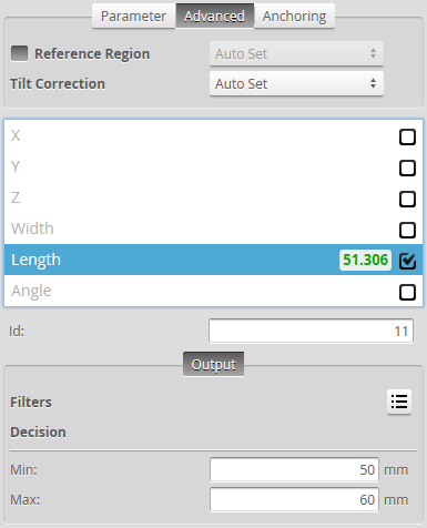
Length Determines the length of the opening. |
|
|
Z Angle Determines the angle (rotation) around the normal of the alignment plane. |
|


| Type | Description |
|---|---|
| Center Point |
The center point of the opening. The Z position of the center point is at the Z position of the surrounding surface. |

|
For more information on geometric features, see Geometric Features. |
| Parameter | Description |
|---|---|
|
Source |
The sensor |
|
Type |
Rounded Slot, Rectangle. |
|
Nominal Width |
Nominal width of the opening. |
|
Nominal Length |
Nominal length of the opening. |
|
Nominal Angle |
Nominal angle of the opening. The default orientation is the length of the opening along the X axis.
The diagram above illustrates the case where the surface is not tilted. When the surface is tilted, the orientation is defined with respect to the normal of the surface, not with respect to the X-Y plane |
|
Nominal Radius |
Nominal radius of the opening ends. If the opening type is set to rectangular, the radius setting is disabled. The opening has an oval shape if the radius is equal to ½ of the width. The opening is a rounded rectangle when the radius is less than ½ of the width.
|
|
Width Tolerance |
The maximum variation from the nominal width (+/- from the nominal value). |
|
Length Tolerance |
The maximum variation from the nominal length (+/- from the nominal value). |
|
Angle Tolerance |
The maximum variation from the nominal orientation (+/- from the nominal value). |
|
Partial Detection |
Enable if only part of the opening is within the measurement region. If disabled, the opening must be completely in the region of interest for results to be valid. |
|
Depth Limit |
Data below this limit (relative to the surface) is excluded from the |
|
Region |
The region to which the tool's measurements will apply. For more information, see Regions. |
|
Reference Regions |
The tool uses the reference regions to calculate the Z position of the
When the Reference Regions setting is disabled, the tool measures the
With one or more reference regions, the algorithm calculates the Z positions as the average values of the data within the regions. When you place the reference region manually, all of the data is used, whether the data is inside or outside the opening. You should place the reference region carefully. |
|
Tilt Correction |
Tilt of the target with respect to the alignment plane. Autoset: The tool automatically detects the tilt. The measurement region to cover more areas on the surface plane than other planes. Custom: You must enter the X and Y angles manually in the X Angle and Y Angle parameters (see below). |
|
X Angle Y Angle |
The X and Y angles you must specify when Tilt Correction is set to Custom. You can use the Surface Plane tool's X Angle and Y Angle measurements to get the angle of the surrounding surface, and then copy those measurement's values to the X Angle and Y Angle parameters of this tool. |
|
Filters |
The filters that are applied to measurement values before they are output. For more information, see Filters. |
|
Decision |
The Max and Min settings define the range that determines whether the measurement tool sends a pass or fail decision to the output. For more information, see Decisions. |


| Anchor | Description |
|---|---|
|
X |
Lets you choose the X |
|
|
A measurement must be enabled in the other tool for it to be available as an anchor. The anchor measurement should also be properly configured before using it as an anchor. |
|
|
For more information on anchoring, see Measurement Anchoring. |
Measurement Region
The center and the two sides and ends of the opening must be within the measurement region, even if Partial Detection is enabled.
