Stitch

|
This tool is not supported on A and B revision Gocator 2100 and 2300 sensors that are not accelerated (either by a PC-based application or by GoMax). The tool is supported in emulator scenarios. |
The Stitch tool lets you combine up to 24 frames of scans into a single Surface scan. This lets you get a much larger scan volume with fewer sensors (either in a single sensor system or a multi-sensor system). For each scan, you can specify not only X, Y, and Z offsets (translations), but also X, Y, and Z angles (rotations), defining its relationship with the others. This means that when the sensor system is mounted to a robot, or if you are using, for example, an X-Y table, you can get a complete scan with fewer sensors. The resulting combined scan can then be used as input by any other Surface or Feature tool from its Stream drop-down.
The tool performs rotation first, and then translation.
You cannot define sections on the combined scan; for more information on sections, see Sections.

|
The tool combines data simply by overwriting in sequence: it performs no averaging or blending. The tool also performs no fitting. |

|
Results are only as accurate as the motion system. |

|
Seams are often seen in combined data in stitching performed in anything other than along the Y axis. |
The tool returns one measurement, which simply indicates the number of scans successfully added to the combined scan data.
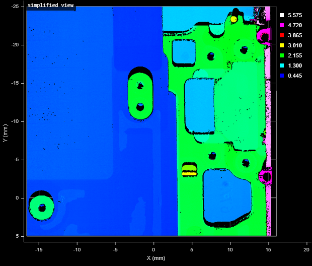
The following shows three individual frames:

In the following, the tool has combined the frames into a single surface.


Measurement Panel
For information on adding, managing, and removing tools and measurements, as well as detailed descriptions of settings common to most tools, see Tools Panel.
Measurements, Data, and Settings
| Measurement |
|---|
|
Captured Indicates the number of scans successfully added to the combined surface scan. |

|
Only one of the following data types will contain data, depending on whether Uniform Spacing is enabled. For more information, see Scan Modes. |
| Type | Description |
|---|---|
|
Stitched Surface |
The stitched surface scan, available for use as input in the Stream drop-down in other tools. Contains uniform data only and is empty if Uniform Spacing is disabled. |
|
Stitched Raw Surface |
The stitched surface scan, available for use as input in the Stream drop-down in other tools. Contains point cloud data only and is empty if Uniform Spacing is enabled. |
| Parameter | Description |
|---|---|
|
Source |
The sensor |
|
Surface Count |
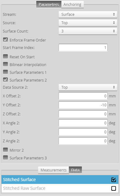
The number of scans to combine into a single surface. For each, a "Surface Parameters" section is added. The tool accepts setting the number of scans to one: in this case it, behaves like a transform tool. |
|
Enforce Frame Order |
Restricts the stitching for specific frame indexes, starting at the frame indicated in Start Frame Index. If unchecked, an Operation drop-down is displayed (see below). This setting is disabled if you attempt to stitch data from individual scans acquired using the Snapshot button (that is, all frame indexes are at 1). |
|
Operation |
If Enforce Frame Order is disabled, the Operation drop-down is displayed. One of the following:
|
|
Reset On Start |
Clears buffers for the stitched surface when the sensor is started. Useful for situations where the sensor is started and stopped frequently (to capture a small number of frames), rather than starting the sensor and letting it run for a long period. Enable this parameter to prevent data from a previous capture session being stitched with data from the current capture session. |
|
Bilinear Interpolation |
Evaluates the height of each transformed point (through translation or rotation) based on its neighbors. More precise, but has an impact on performance. |
|
Surface Parameters {n} |
For each scan to be added to the combined surface scan, a Surface Parameters checkbox is added. To configure the parameters of the individual surfaces, check the box and configure the settings. Unchecking the checkbox does not disable the scan or its settings. The following settings are available:
|
|
Filters |
The filters that are applied to measurement values before they are output. For more information, see Filters. |
|
Decision |
The Max and Min settings define the range that determines whether the measurement tool sends a pass or fail decision to the output. For more information, see Decisions. |
| Anchor | Description |
|---|---|
|
X |
Lets you choose the X |
|
Z angle |
Lets you choose the Z Angle measurement of another tool to use as an angle anchor for this tool. |

|
A measurement must be enabled in the other tool for it to be available as an anchor. The anchor measurement should also be properly configured before using it as an anchor. |

|
For more information on anchoring, see Measurement Anchoring. |