Bounding Box Advanced

|
This tool is not supported on A and B revision Gocator 2100 and 2300 sensors that are not accelerated (either by a PC-based application or by GoMax). The tool is supported in emulator scenarios. |
Like the Bounding Box tool (see Bounding Box), the Bounding Box Advanced tool provides measurements related to the smallest box that contains the scan data from a part (for example, X position, Y position, width, length, etc.). However, this version of the tool also lets you get the height of bounding box relative to the Z origin (typically the conveyor on which the target is sitting). This lets you determine, for example, the height of a box or other container on the conveyor as part of a product packaging process. New settings also let you easily filter out noise that can affect height, width, and length measurements.
A bounding box can be vertical or rotated. A vertical bounding box provides the absolute position from which the Position centroids tools are referenced.
|
|
The vertical bounding box X and Y correspond to the part frame of reference origin. For this reason all X and Y measurements (except Bounding Box Global X and Global Y) are referenced to this point when Frame of Reference on the Part Detection panel is set to Part. See Part Detection for more information. |
|
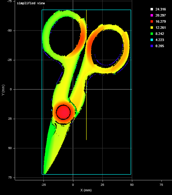
2D View |
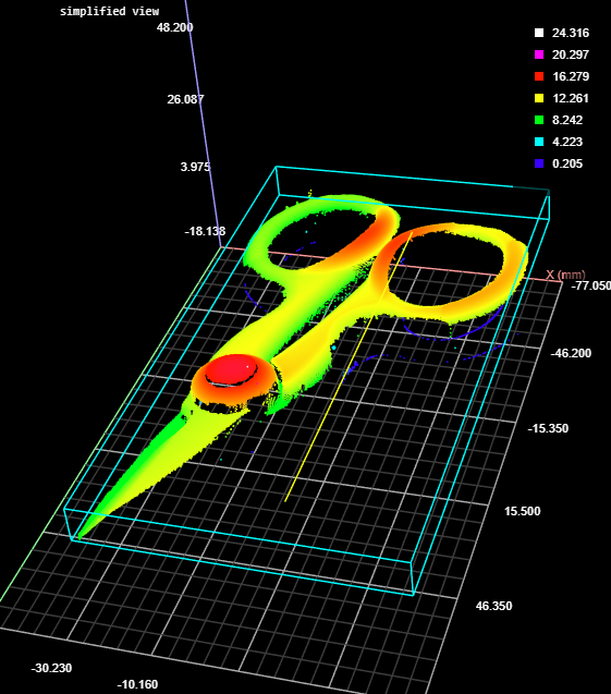
3D View |
Measurement Panel
For information on adding, managing, and removing tools and measurements, as well as detailed descriptions of settings common to most tools, see Tools Panel.
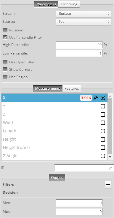
Measurements, Features, and Settings
| Measurement | Illustration |
|---|---|
|
X Determines the X position of the center of the bounding box that contains the part. The value returned is relative to the part. |
|
|
Y Determines the Y position of the center of the bounding box that contains the part. The value returned is relative to the part. |
|
|
Z Determines the Z position of the center of the bounding box that contains the part. The value returned is relative to the part. |
|
|
Width Determines the width of the bounding box that contains the part. When the Rotation setting is disabled, the bounding box is the smallest rectangle whose sides are parallel to the X and Y axes. Width is on the X axis. When Rotation is enabled, the width is the smaller side dimension. |
|
|
Length Determines the length of the bounding box that contains the part. When the Rotation setting is disabled, the bounding box is the smallest rectangle whose sides are parallel to the X and Y axes. Length is on the Y axis. When Rotation is enabled, the length is the longer side dimension. |
|
|
Height Determines the height of the bounding box that contains the part. |
|
|
Height from 0 Determines the distance from the top of the bounding box to the Z origin (Z = 0). |
|
| Z Angle
Determines the rotation around the Z axis and the angle of the longer side of the bounding box relative to the X axis. If Rotation is not enabled, the measurement returns 90.000 degrees. In order to use this measurement for angle anchoring, you must enable Rotation; for more information on anchoring, see Measurement Anchoring. |
|


| Type | Description |
|---|---|
|
Center |
The center point of the bounding box. |
|
|
For more information on geometric features, see Geometric Features. |
| Type | Description |
|---|---|
|
Diagnostics Surface |
A surface useful for evaluating the impact of the open filter. For more information, see Use Open Filter. |
| Parameter | Description |
|---|---|
|
Source |
The sensor |
| Rotation |
A bounding box can be vertical or rotated. A vertical bounding box provides the absolute position from which the part's Position centroid measurements are referenced. Check the Rotation setting to select rotated bounding box. |
|
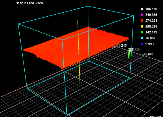
Use Percentile Filter |
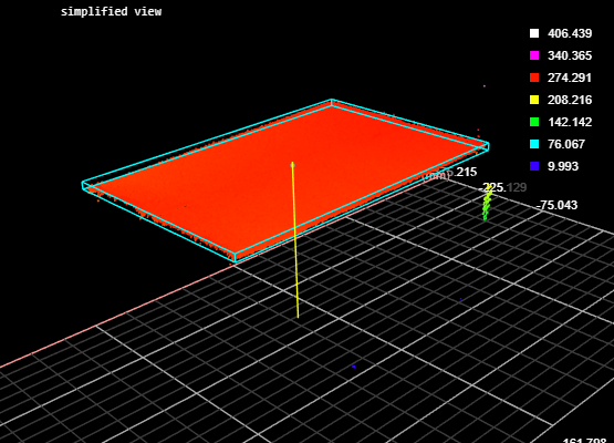
Limits the bounding box to data points along the Z axis between the values you set in High Percentile and Low Percentile, which are displayed when you choose this option. Use this setting to obtain more "robust" height measurements. This setting is useful to exclude noise that would otherwise cause inaccurate height measurements. For example, in the following scan of a box, without excluding a small percentage of the highest data points, data points caused by noise to the upper right produces an inaccurate height measurement of the box of 406.457 mm.
When High Percentile is set to 99%, the highest 1 percent of data points is excluded from the placement of the bounding box, and an accurate height of the target box of 270.477 mm is returned.
|
|
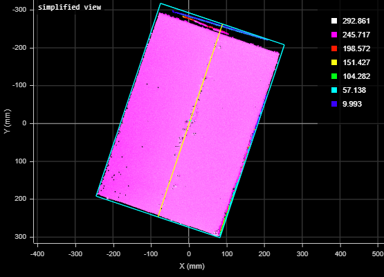
When enabled, this setting lets you set the value of Kernel Size for an open morphological operation applied to the scan data on the XY plane, letting you achieve "robust" width and length measurements. This filter removes noise or small objects from scan data, while keeping the shape and size of the larger objects in the scan data. For example, in the following, noise along the edge at the top of the data viewer results in an inaccurate length measurement.
When the filter is set to an appropriately sized kernel (here, 11 points), the noise is excluded from the calculation of the bounding box, and an accurate length is returned.
Use the Diagnostics Surface on the Data tab to evaluate the impact of the open filter, to avoid removing too much data. |
|
|
Show Corners |
When enabled, outputs the corners of the fitted bounding box as geometric features (Corner {n}). |
|
Use Region |
When enabled, displays additional settings to let you set a region (see below). |
|
Region Type
Inner Circle Diameter
Inner Ellipse Major Axis Inner Ellipse Minor Axis
Sector Start Angle Sector Angle Range
Mask Source
Low Threshold High Threshold |
When you enable Use Region, the tool displays additional settings related to the measure region type. For details on flexible regions and their settings, see Flexible Regions. For general information on regions and the difference between standard and "flexible" regions, see Regions. |
|
Filters |
The filters that are applied to measurement values before they are output. For more information, see Filters. |
|
Decision |
The Max and Min settings define the range that determines whether the measurement tool sends a pass or fail decision to the output. For more information, see Decisions. |

| Anchor | Description |
|---|---|
|
X |
Lets you choose the X |
|
Z angle |
Lets you choose the Z Angle measurement of another tool to use as an angle anchor for this tool. |
|
|
A measurement must be enabled in the other tool for it to be available as an anchor. The anchor measurement should also be properly configured before using it as an anchor. |
|
|
For more information on anchoring, see Measurement Anchoring. |