Bounding Box
The Bounding Box tool provides measurements related to the smallest box that contains the scan data from a part (for example, X position, Y position, width, length, etc.).

|
If you need to measure the height of the target relative to the Z = 0 reference (such as if you want to measure the height of a box or other container), use the Surface Bounding Box Advanced tool; for more information, see Bounding Box Advanced. |
A bounding box can be vertical or rotated. A vertical bounding box provides the absolute position from which the Position centroids tools are referenced.
|
|
The vertical bounding box X and Y correspond to the part frame of reference origin. For this reason all X and Y measurements (except Bounding Box Global X and Global Y) are referenced to this point when Frame of Reference on the Part Detection panel is set to Part. See Part Detection for more information. |
|
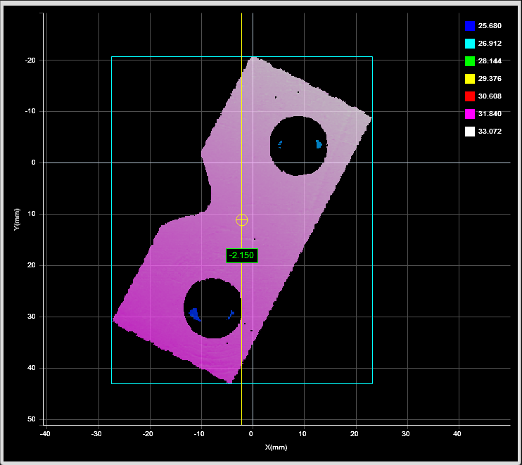
2D View |
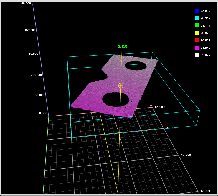
3D View |

Measurement Panel
For information on adding, managing, and removing tools and measurements, as well as detailed descriptions of settings common to most tools, see Tools Panel.
Measurements, Features, and Settings
| Measurement | Illustration |
|---|---|
|
X Determines the X position of the center of the bounding box that contains the part. The value returned is relative to the part. |
|
|
Y Determines the Y position of the center of the bounding box that contains the part. The value returned is relative to the part. |
|
|
Z Determines the Z position of the center of the bounding box that contains the part. The value returned is relative to the part. |
|
|
Width Determines the width of the bounding box that contains the part. When the Rotation setting is disabled, the bounding box is the smallest rectangle whose sides are parallel to the X and Y axes. Width is on the X axis. When Rotation is enabled, the width is the smaller side dimension. |
|
|
Length Determines the length of the bounding box that contains the part. When the Rotation setting is disabled, the bounding box is the smallest rectangle whose sides are parallel to the X and Y axes. Length is on the Y axis. When Rotation is enabled, the length is the longer side dimension. |
|
|
Height Determines the height of the bounding box that contains the part. |
|
| Z Angle
Determines the rotation around the Z axis and the angle of the longer side of the bounding box relative to the X axis. If Rotation is not enabled, the measurement returns 90.000 degrees. In order to use this measurement for angle anchoring, you must enable Rotation; for more information on anchoring, see Measurement Anchoring. |
|
| Global X*
Determines the X position of the center of the bounding box that contains the part on the surface from which the part was extracted. |
|
| Global Y*
Determines the Y position of the center of the bounding box that contains the part on the surface from which the part was extracted. If the part is extracted from a continuous surface, the Y origin of that surface is at the encoder starting position. |
|
| Global Z Angle*
Determines the rotation of the longer side of the bounding box around the Z axis on the surface from which the part was extracted. If part matching is enabled, the returned value represents the rotation of the part before part matching rotates it. If Rotation is not enabled, the measurement returns 90.000 degrees. |
|


|
|
*These measurements are mostly useful with parts extracted from a surface. For more information on parts, see Part Detection. |
| Type | Description |
|---|---|
|
Center Point |
The center point of the bounding box. |
|
Box Axis Line |
The axis of the bounding box. |
|
|
For more information on geometric features, see Geometric Features. |
| Parameter | Description |
|---|---|
|
Source |
The sensor |
| Rotation |
A bounding box can be vertical or rotated. A vertical bounding box provides the absolute position from which the part's Position centroid measurements are referenced. Check the Rotation setting to select rotated bounding box. |
| Asymmetry Detection |
Resolves the orientation of an object over 360 degrees. The possible values are: 0 – None 1 – Along Major Axis 2 – Along Minor Axis This setting is only visible if Rotation is checked. |
|
Region |
The region to which the tool's measurements will apply. For more information, see Regions. |
|
Filters |
The filters that are applied to measurement values before they are output. For more information, see Filters. |
|
Decision |
The Max and Min settings define the range that determines whether the measurement tool sends a pass or fail decision to the output. For more information, see Decisions. |
| Anchor | Description |
|---|---|
|
X |
Lets you choose the X |
|
Z angle |
Lets you choose the Z Angle measurement of another tool to use as an angle anchor for this tool. |
|
|
A measurement must be enabled in the other tool for it to be available as an anchor. The anchor measurement should also be properly configured before using it as an anchor. |
|
|
For more information on anchoring, see Measurement Anchoring. |