Edge
The Edge tool fits a line to a straight edge in the scan data, using either height map or intensity data. The tool can search for an edge using either a step (an abrupt change in the data) or a corner (a contiguous change in the shape of surface). The tool's settings help fit the line when multiple potential edges are in the region of interest. After the tool locates an edge, it returns the position (X, Y, and Z) of the center of the edge line in the region of interest. The tool also returns its angle around the Z axis, the step height between the upper and lower surfaces adjacent to the edge, minimum and maximum error points to either side of the line, and a point count.
You can use the Z Angle measurement of the edge line with some tools to perform angle anchoring, compensating for minor part rotations around the Z axis, greatly increasing repeatability between part scans; for more information see Measurement Anchoring.
The minimum and maximum errors are useful for calculating a straightness value (using a script tool, for example; for more information, see Script).
The tool can also generate edge line and center point geometric features that Feature tools can take as input for measurement. For more information on Feature tools, see Feature Measurement.
|
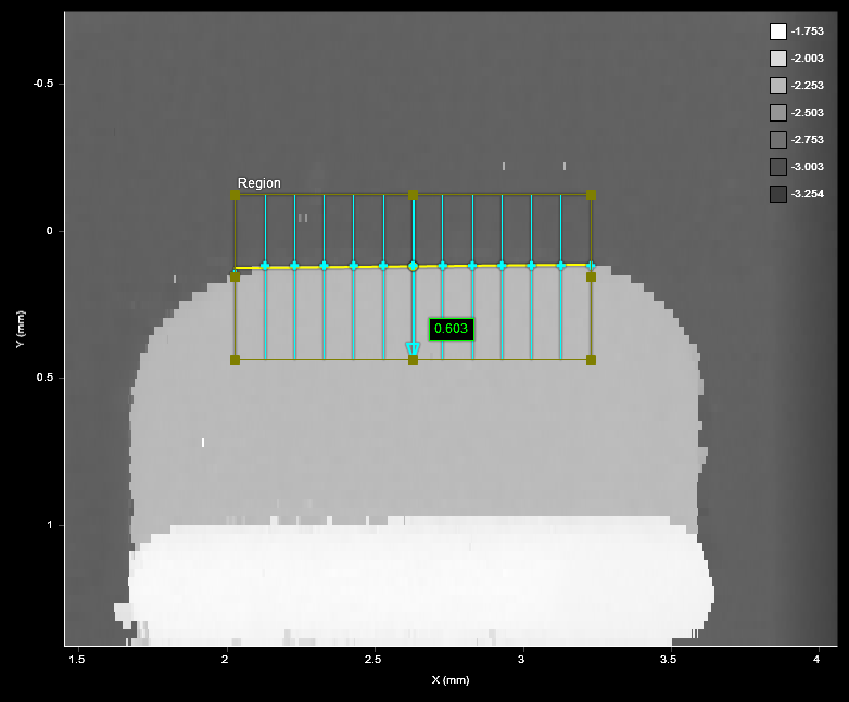
2D View |
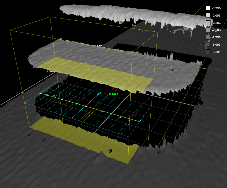
3D View |
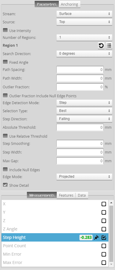
Measurement Panel
For information on adding, managing, and removing tools and measurements, as well as detailed descriptions of settings common to most tools, see Tools Panel.
Paths and Path Profiles
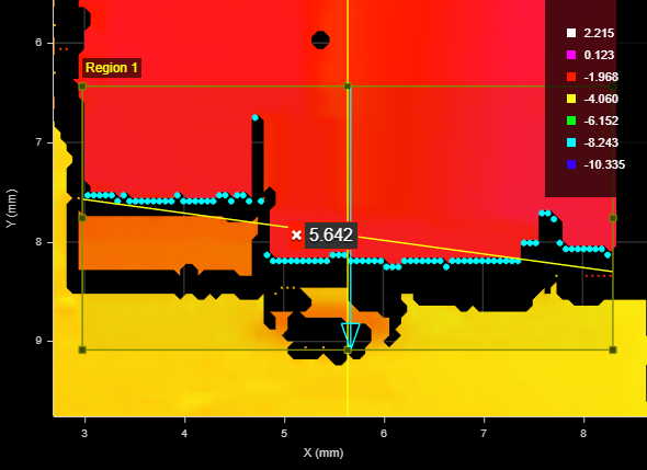
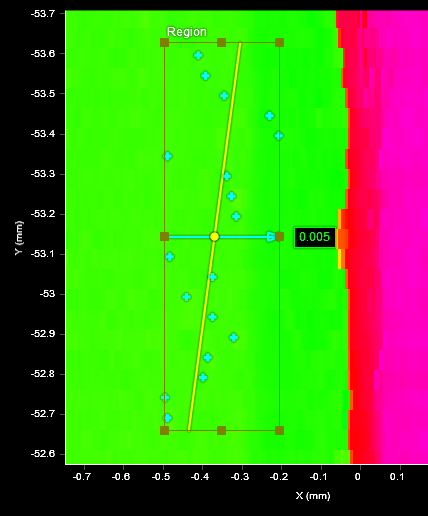
To fit an edge line to the scan data, the Surface Edge tool overlays evenly spaced, parallel paths (light blue lines in the interface; see below) in the defined region of interest.
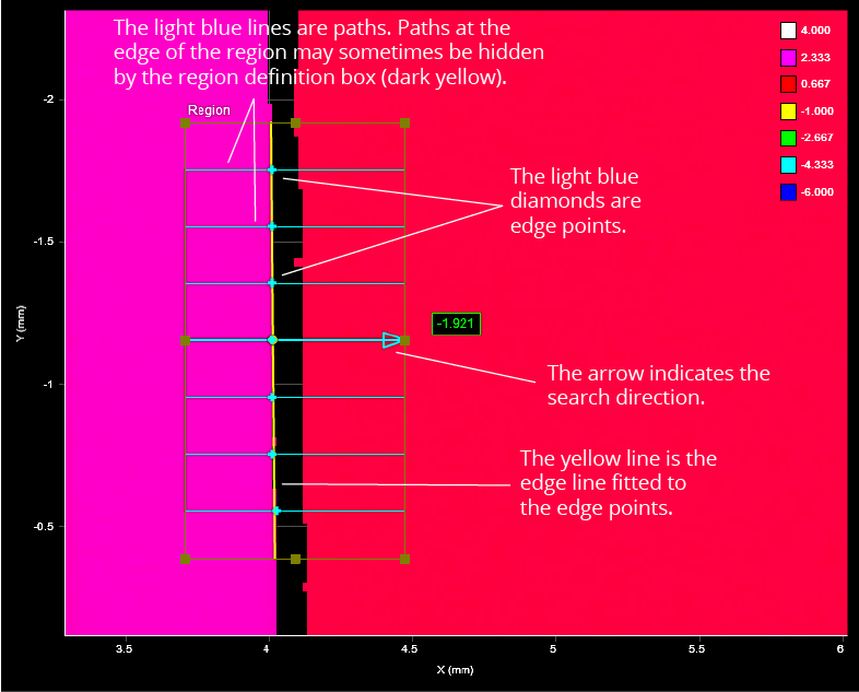
For each path, a profile is generated internally from the height map’s data points that fall under or, optionally, near the path. The tool then examines each path profile for steps (changes in height) that meet the criteria set by the tool’s settings, such as minimum height, direction (whether it is rising or falling), and so on.

For the step on each path profile that matches the settings, the tool places an edge point between the upper and lower area (light blue diamonds in the interface). The tool then fits a line to those edge points (yellow line in the interface). You can choose the orientation of the paths around the Z axis to accommodate different edge orientations.
Measurements, Features, Data, and Settings
| Measurement | Illustration |
|---|---|
|
X Returns the X position of the center point of the fitted edge line. |
|
|
Y Returns the Y position of the center point of the fitted edge line. |
|
|
Z Returns the Z position of the center point of the fitted edge line. |
|
|
Z Angle Returns the rotation, around the Z axis, of the fitted edge line. Rotating the measurement region has no impact on the angle that is returned unless a different edge is detected. Useful for using minor variations in the rotation of an edge on target as an anchor for other measurements. For more information, see Measurement Anchoring. |
|
|
Step Height Returns the height of the step, calculated by averaging the step heights of all of the path profiles. (When Use Intensity is enabled, the value returned is the difference in intensity.) This measurement returns Invalid when Edge Detection Mode is set to Corner. |
|
|
Min Error Max Error These measurements return the distances of the point furthest before the line (Min Error) and the point furthest after the line (Max Error), based on the search direction specified in the tool. The measurements ignore points excluded using the |
|
|
Point Count The number of points used to fit the line. Useful for determining if the number of points is above an acceptable minimum. |

|


| Type | Description |
|---|---|
|
Edge Line |
The fitted edge line. |
|
Center Point |
The intersection point of the fitted edge line and the line representing the search direction through the center of the region of interest. |
|
Edge Plane |
A plane on the XZ axes at the fitted edge line. |

|
For more information on geometric features, see Geometric Features. |
| Type | Description |
|---|---|
|
Profile Point Cloud Profile Region {n} |
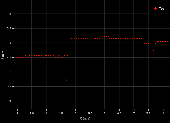
A point cloud profile (Profile Point Cloud) and one or more uniform spacing profiles (Profile Region {n}) representing the edge, respectively, made up of the tool's edge points. The XY positions of the edge points on the surface (cyan dots below) are represented as the XZ positions of the profile points, where X => X and Y => Z. Given the following edge, the resulting profile is shown further below:
The profile is mirrored vertically when compared to the edge: Note how the single edge point toward the top of Region 1 in the surface data above is at the bottom of the extracted profile (below).
|
| Parameter | Description |
|---|---|
|
Source |
The sensor |
|
Number of Regions |
The number of regions the tool will use to fit the line. You must configure each region (see Region {n}). Using multiple regions allows you to fit a line to an edge that is not straight along its entire length or that is not continuous. |
|
The region or regions the tool uses to fit a line. For more information, see Regions. You can configure the Z Angle of each region independently to accommodate the particularities of the feature or target (for example, to exclude unwanted scan data next to one of the regions in the fitting of the line to the edge). |
|
|
Search Direction |
The search direction for steps, specified as an orientation around the Z axis, relative to the X axis. Can be 0, 90, 180, or 270 degrees. Choose a value that is roughly perpendicular to the edge on the target. The direction is indicated by a light blue arrow in the data viewer. |
|
Fixed Angle |
When this option is enabled, the value in Fixed Angle Value replaces the value the Z Angle measurement returns. Useful when the angle of the feature is known and noise in the scan data could otherwise cause the measurement to return an incorrect angle. |
|
Fixed Angle Value |
The value the tool uses to locate the edge and returns for the Z Angle measurement. You must enable Fixed Angle to set this value. |
|
Path Spacing |
Sets the spacing between paths in the measurement region used to extract the profiles that determine the edge. A higher number of paths results in a higher number of edge points, which makes the fitting of the edge line more accurate. However, a higher number of edge points results in a greater tool execution time. When Path Spacing is set to 0, the resolution of the scan data is used as the basis for spacing. No paths are displayed in the data viewer in this case. |
|
Path Width |
The size of the windows perpendicular to the path used to calculate an average for each data point on a path profile. Useful to average out noise along the path caused by reflections, and so on.
If Path Width is set to 0, no averaging is performed (only the data point under the path is used). For averaging along the path, use Step Smoothing (see below). |
|
Outlier Fraction |
The percentage of outlier points to exclude. Setting this to a small value can help the tool fit the line better to the edge.
Outlier Fraction set to a low value: rejected outlier edge points are dark blue. |
|
Edge Detection Mode |
One of the following: Step or Corner. Step: Searches for steps on each path profile. For additional settings when you choose this mode, see Step Edge Detection Mode Parameters. Corner: Searches for slopes on each path profile. When you choose this mode, several of the tool's parameters are hidden. |
|
Selection Type Corner Type |
Determines which step (when Edge Detection Mode is set to Step) or corner (when Edge Detection Mode is set to Corner) the tool uses on each path profile when there are multiple steps or corners in the profile. An edge point is placed on each chosen step or corner. Steps must pass the criteria of the tool's Absolute Threshold, Step Direction, and Relative Threshold settings (see Step Edge Detection Mode Parameters). Best: Selects the greatest step or corner on each path profile. First: Selects the first step or corner on each path profile. Last: Selects the last step or corner on each path profile. When Edge Detection Mode is set to Corner, the following additional options are available in Corner Type: Top: Selects the top-most corner on each path profile. Bottom: Selects the bottom-most corner on each path profile. |
|
Show Detail |
When disabled, hides the light blue path lines and edge points. |
|
Filters |
The filters that are applied to measurement values before they are output. For more information, see Filters. |
|
Decision |
The Max and Min settings define the range that determines whether the measurement tool sends a pass or fail decision to the output. For more information, see Decisions. |

|
|
The following parameters are only displayed if you set Edge Detection Mode to Step. |
|
Use Intensity |
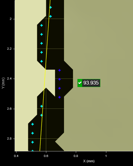
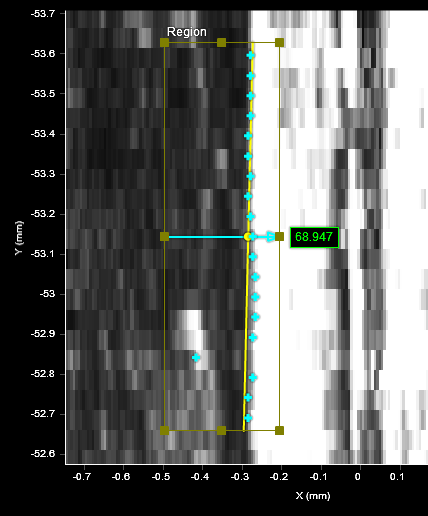
(This setting is only available when Acquire Intensity is enabled in the Scan Mode panel; for more information, see Scan Modes.) Uses intensity data rather than height data to find an edge. Useful when color differences on a flat area of a target, which would not be detected using height map data, are distinct, letting you use the detected "line" as an anchor source or perform geometric feature measurements.
Use Intensity enabled (intensity view): Surface Edge tool finds the edge using intensity data.
Use Intensity disabled (heightmap view of the same area): Surface Edge tool unable to find edge using height data. |
||
|
Step Direction |
Determines whether the expected step rises or falls along the path. Either Rising, Falling, or Rising or Falling. |
||
|
Absolute Threshold |
When Use Intensity is disabled, the setting specifies the minimum height difference between points on a path profile for that step to be considered for an edge point. The setting can be used to exclude smaller steps on a part that should not be considered for an edge, or to exclude height differences caused by noise. When used in conjunction with Relative Threshold, Absolute Threshold is typically set to a small value, greater than the general surface roughness.
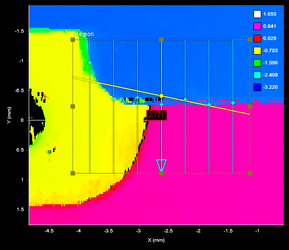
In the image below, when Absolute Threshold is left at the default of 0, all steps are included as possible candidates for an edge, and will be used to fit an edge line. The resulting edge line is angled upward to the left.
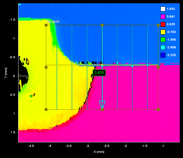
When Absolute Threshold is set to 3 with the same data (see image below), steps going from the yellow to pink regions (roughly 1.37 mm) and from the blue to yellow regions (roughly 2 mm) are excluded. Only steps from the blue to pink regions (roughly 3 mm) are included.
When Use Intensity is enabled, the setting specifies the minimum difference in intensity. (Acquire Intensity must enabled in the Scan Mode panel.) |
||
|
Use Relative Threshold |
When this option is enabled, the Relative Threshold field is displayed. |
||
|
Relative Threshold |
The value for the relative threshold. The tool calculates a relative threshold by scaling the greatest height or intensity difference found on the path profiles by the percentage in Relative Threshold. This lets you configure the tool without knowing the actual step height in advance, and is useful for edges with varying step height. For a height or intensity difference to be considered a valid step, both Absolute Threshold and Relative Threshold must pass. |
||
|
Step Smoothing |
The size of the windows along the path used to calculate an average for each data point on a path profile. The setting is useful for averaging out noise.
If Step Smoothing is set to 0, no averaging is performed (only the data point under the path is used). For averaging perpendicular to the path, use Path Width (see above). |
||
|
Step Width |
The distance, along a path profile, separating the points used to find steps on a path profile.
The setting is useful when you must detect a slope as an edge, rather than a sharply defined edge: setting Step Width to a value greater than the width of the edge ensures that the tool measures the height difference between the flat regions on either side of the edge. As a result, the height of the step is accurately measured, and the edge is correctly located.
|
||
|
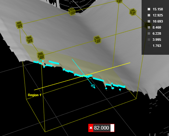
Max Gap |
Fills in regions of missing data caused by an occlusion near the desired edge. Use this setting when continuity on the target is expected. When Max Gap is set to a non-zero value, the tool holds and extends the last data point on the low side next to an edge across a gap of null points, up to the distance specified in Max Gap.
|
||
|
Include Null Edges |
Indicates whether null points (points where no height or intensity value is available, due to dropouts or regions outside of the measurement range) are filled with the value in Null Fill Value as a general “background level.” If Use Intensity (see above) is enabled, the intensity value in Intensity Null Fill Value is also used. A typical example is a discrete part produced by part detection of an object sitting on a flat background. The background is not visible in the part, so the tool assumes that any null region are at the background level.
|
||
|
Null Fill Value |
The height value (in mm) used to replace null points not filled by Max Gap when Include Null Edges is enabled. |
||
|
Intensity Null Fill Value |
The intensity value (0-255) used to replace null points when Include Null Edges and Use Intensity are enabled. |
||
|
Edge Mode |
One of the following: Projected: The line fitted to the edge is projected onto the XY plane. This mode is typically used with an edge that is parallel to the XY plane. (Shown on a sloped edge to illustrate its effect.)
3D: The line fitted to the edge follows the slope of the edge. This mode is typically used with a sloped edge. |


| Anchor | Description |
|---|---|
|
X |
Lets you choose the X |
|
Z angle |
Lets you choose the Z Angle measurement of another tool to use as an angle anchor for this tool. |
|
|
A measurement must be enabled in the other tool for it to be available as an anchor. The anchor measurement should also be properly configured before using it as an anchor. |
|
|
For more information on anchoring, see Measurement Anchoring. |