Segmentation

|
This tool is not supported on A and B revision Gocator 2100 and 2300 sensors that are not accelerated (either by a PC-based application or by GoMax). The tool is supported in emulator scenarios. |
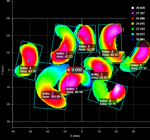
The Segmentation tool separates surface data into "segments," based on the tool's parameters. Segments can be touching and overlapping to a certain degree. The Segmentation tool is especially useful in the food industry, for example to identify food items that are too small or too big, or items that are damaged.
For each segment, the tool returns the X and Y position of its center, its length and width, and its area, as well as several more global measurements, such as maximum / minimum width or length, etc. For a complete list, see below.
The Segmentation tool can also be used as a second stage of processing after part detection. For example, part detection could be used to detect a tray (containing parts), and the Segmentation tool could then separate the parts within the tray. For information on part detection, see Part Detection. For a comparison of part detection, Surface Blob, and Surface Segmentation, see Isolating Parts from Surface Data.
|
|
The Segmentation tool cannot handle large overlaps. |
|
|
The Segmentation tool does not perform template matching. |
|
|
To reduce processing time, consider using the decimation filter. For more information on this filter, see Filters. |
|
2D View |
3D View |

Measurement Panel
For information on adding, managing, and removing tools and measurements, as well as detailed descriptions of settings common to most tools, see Tools Panel.
Measurements, Data, and Settings
| Measurement |
|---|
|
Count Returns the total number of segments identified, based on the tool's parameters. |
|
Min Dimension Max Dimension The minimum and maximum dimensions among all of the identified segments. |
|
Mean Width Mean Length The mean width and length of the segments, respectively. |
|
Min Area Max Area The minimum and maximum area among all of the identified segments. |
|
Sum Area The sum of the areas of the segments. |
|
Mean Area The mean area of the segments. |
|
Min Height Max Height The minimum and maximum heights among all of the identified segments. |
|
Mean Height The mean height of the segments. |
|
X Center {n} Y Center {n} The X and Y positions of the center of a part segmented from the surface. The Number of Part Outputs setting determines the number of measurements listed in the Measurements tab. |
|
Z Average {n} Z Min {n} Z Max {n} The average, minimum, and maximum Z value of a part segmented from the surface. The Number of Part Outputs setting determines the number of measurements listed in the Measurements tab. |
|
Width {n} Length {n} The width and length of a part segmented from the surface. These are always the major and minor axis of a part, respectively. The Number of Part Outputs setting determines the number of measurements listed in the Measurements tab. |
|
The area of a part segmented from the surface. The area is calculated using the contour of the part and resampling. For this reason, areas calculated using the Surface Volume tool will produce different measurements; for more information, see Area. |
| Type | Description |
|---|---|
| Center Point {n} |
The point representing the center of a segmented part. The Number of Part Outputs setting determines the number of point geometric features listed in the Features tab. |
| Type | Description |
|---|---|
|
Segments Array |
An array containing the segments. For an example of how to access this data from an SDK application or a GDK tool, see the appropriate sample in the SDK samples; for more information, see Setup and Locations. |
|
Diagnostics Surface |
Surface data you can use to evaluate the impact of the tool's kern size and iteration settings, which the tool uses to separate potential segments. |
|
Surface {n} |
Surface data corresponding to each segmented part. |
| Parameter | Description |
|---|---|
|
Source |
The sensor that provides data for the tool's measurements. |
|
Use Intensity |
Causes the tool to use intensity. The option is only displayed if intensity data is available. |
|
Use Region |
Only displayed on older instances of this tool. Newer instances use "flexible regions" (see the parameters below in this table). Indicates whether the tool uses a user-defined region. If this option is not checked, the tool uses data from the entire active area. |
|
Number of Regions
Mask Type {n} / Region Type {n}
Inner Circle Diameter
Inner Ellipse Major Axis Inner Ellipse Minor Axis
Sector Start Angle Sector Angle Range
Mask Source
Low Threshold High Threshold |
Only displayed on newer instances of this tool. When you enable Use Region, the tool displays additional settings related to the measure region type. For details on flexible regions and their settings, see Flexible Regions. For general information on regions and the difference between standard and "flexible" regions, see Regions. |
|
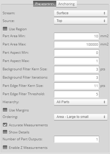
Part Area Min Part Area Max |
The minimum and maximum areas in square millimeters for a part of the scan data to be identified as a segment. |
|
Part Aspect Min Part Aspect Max |
The minimum and maximum aspect ratios (minimum axis length in mm) / (maximum axis length in mm) of the best fit ellipse to the segment contour points for a segment to qualify to be added to the list of found segments. |
|
Background Filter Kern Size Background Filter Iterations |
These settings perform background separation. The greater each of these values is, the more separation will be achieved. You must find a balance that removes noise adequately without degrading the segment find quality. |
|
Part Edge Filter Kern Size |
Use this value to adjust the “granularity” of the part edge detection. |
|
Part Edge Filter Threshold |
Controls the separation of the parts, increasing the gap between the parts so that they can be detected more easily. |
|
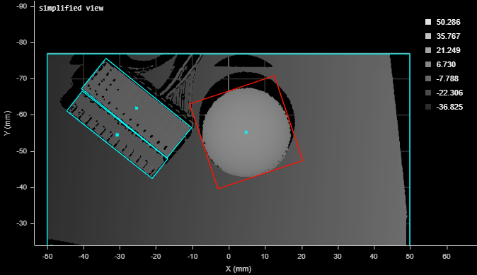
Hierarchy |
Use this setting to detect segments when they are surrounded by background data. Choose one of the following: All Parts or External Parts. All Parts This option lets you segment parts with surrounding background data. This is the default behavior in firmware 6.0 and later. Jobs created using firmware 5.3 SR1 or earlier default to External Parts (see below). For example, in the following image, with All Parts selected, the sphere is correctly segmented from the surrounding background.
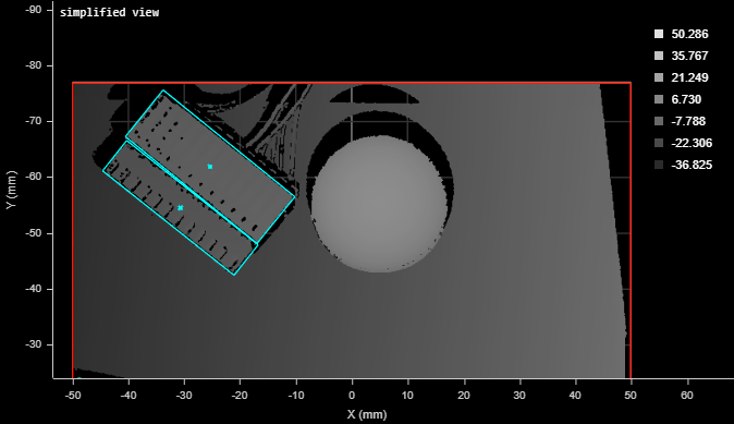
Note that this option may result in "over-segmentation": the tool may segment a part into two segments. External Parts In the following image, with External Parts, the sphere is not identified as a segment because of the surrounding background. It is treated as part of a large segment that includes all of the background. (This "segment" is indicated by a red border that shows it's currently selected. Note that to exclude this kind of segment, you can set a maximum acceptable part area in the tool.)
|
|
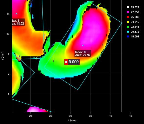
Use Margins |
When enabled, discards parts that are too close to the edge of the scanning area or the region, based on the left, right, top, and bottom values. The tool filters the parts using the center point. In the following, a part's center point is close to the edge of the XY scan area; the right margin is set to 0, so the part is not discarded. (Total part count is 9.)
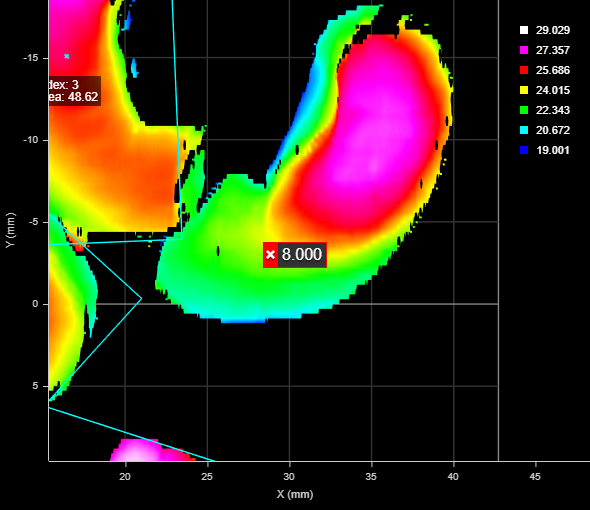
In the following, the right margin has been set to 10 mm. Because the center point of the part is now within the margin, the tool discards the part. (Total part count is reduced to 8.)
|
|
Ordering |
Orders the measurements, features, and surface data of the individual parts output by the tool. Choose one of the following:
|
|
Accurate Measurements |
Returns more accurate width, height, and area measurements, as well as a better Surface output, but the trade-off is greater processing time. If you only need center points or the number of parts, disable this parameter for faster processing. |
|
Show Details |
Toggles whether the tool displays the index and area of each individual part. |
|
Number of Part Outputs |
Determines the number of parts the tool outputs as measurements, features (center points of parts), and surface data. Currently limited to 200 parts. |
|
Enable Z Measurements |
When this parameter is enabled, the tool outputs the minimum, maximum, and average Z value of each segment. This can be useful in applications where a large number of segments is expected when you need these Z measurements for each one. |
|
Filters |
The filters that are applied to measurement values before they are output. For more information, see Filters. |
|
Decision |
The Max and Min settings define the range that determines whether the measurement tool sends a pass or fail decision to the output. For more information, see Decisions. |
| Anchor | Description |
|---|---|
|
X or Z |
Lets you choose the X or Z measurement of another tool to use as a positional anchor for this tool. |
|
Z angle |
Lets you choose the Z Angle measurement of another tool to use as an angle anchor for this tool. |
|
|
A measurement must be enabled in the other tool for it to be available as an anchor. The anchor measurement should also be properly configured before using it as an anchor. |
|
|
For more information on anchoring, see Measurement Anchoring. |