Blob

|
This tool is not supported on A and B revision Gocator 2100 and 2300 sensors that are not accelerated (either by a PC-based application or by GoMax). The tool is supported in emulator scenarios. |
The Surface Blob tool lets you detect surface defects, such as uneven or excess material, gouges, or blemishes, on a relatively uniform or flat background, in either 3D height map data or intensity data. It can also extract targets from the surface. The tool optionally lets you set its height threshold relative to a user-defined reference region. It also lets you use a reference plane to correct for a minor tilt of the target surface (up to 10 degrees); this lets you detect low or shallow defects that would otherwise not be detectable due to a tilt.
|
|
The Surface Blob tool provides functionality similar to the Surface Segmentation tool. For a comparison of these tools and the part detection capabilities you can configure on the Scan page, see Isolating Parts from Surface Data. For information on the Surface Segmentation tool, see Segmentation. |
The tool first filters data based on a height or intensity threshold (above or below it), and then uses configurable morphological operations to better isolate parts. Finally, the tool uses various size- and shape-based filters that let you exclude or include the expected defects or the targets you need (potential blobs).
The tool lets you configure the maximum number of "blobs" to output, and returns the total blob count, and for each blob, the X and Y center, the width and length, and the area. The center point of each blob is available as a geometric feature. The blobs themselves are available in an array that can be accessed and processed by an SDK application or a GDK tool. For more information on the SDK, see GoSDK. For more information on the GDK, see GDK.
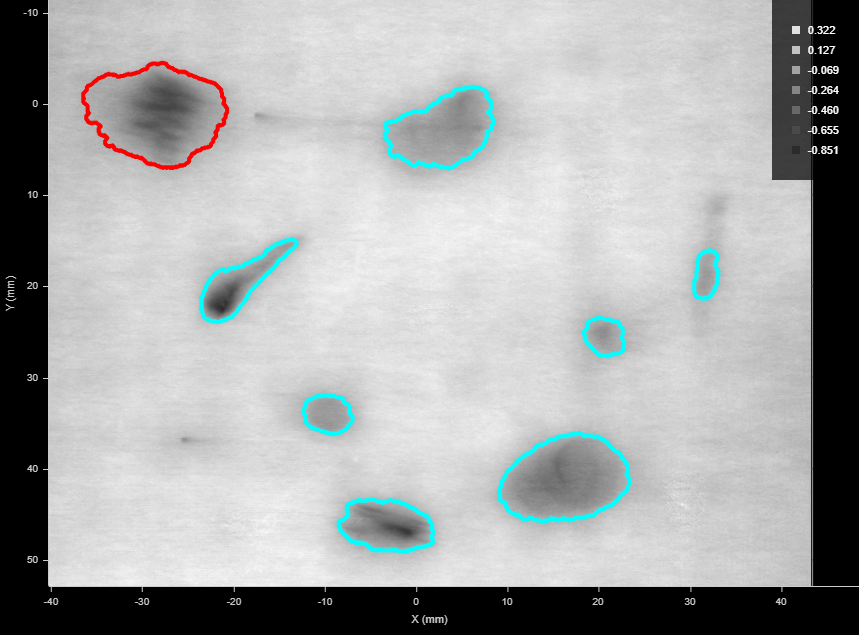
Several dents outlined on a surface. The currently selected blob is outlined in red. (Grayscale heightmap mode is used to better see the outlines.)
Note that knowing the rough size and shape of the kinds of detects you expect is important when you are configuring the open and close kernels and the tool's filters.
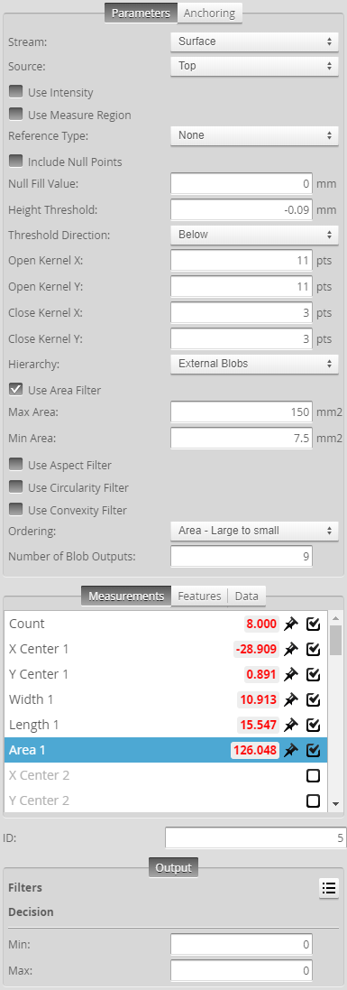
Tool configuration panel
For information on adding, managing, and removing tools and measurements, as well as detailed descriptions of settings common to most tools, see Tools Panel.
Measurements, Data, and Settings
| Measurement |
|---|
|
Count Returns the total number of blobs identified, based on the tool's parameters. |
|
Area {n} The area of a blob. The area is calculated using the contour of the blob and resampling. For this reason, areas calculated using the Surface Volume tool will produce different measurements; for more information, see Area. |
|
X Center {n} Y Center {n} The X and Y positions of the center of mass of a blob extracted from the surface. The Number of Blob Outputs setting determines the number of measurements listed in the Measurements tab. |
|
Z Average {n} Z Min {n} Z Max {n} The average, minimum, and maximum Z value of a blob extracted from the surface. The Number of Part Outputs setting determines the number of measurements listed in the Measurements tab. |
|
Length {n} Width {n} The length and width of the rotated bounding box that encapsulates the blob extracted from the surface. These are always the major and minor axis of a blob, respectively. The Number of Blob Outputs setting determines the number of measurements listed in the Measurements tab. |
| Type | Description |
|---|---|
|
Center Point {n} |
The point representing the center of a blob. |
| Type | Description |
|---|---|
|
Blobs Array |
An array containing the blobs. For an example of how to access this data from an SDK application or a GDK tool, see the appropriate sample in the SDK samples; for more information, see Setup and Locations. |
|
Diagnostics Surface |
Surface data you can use to evaluate the impact of the tool's parameters, before the tool's filters are applied, to properly separate the areas corresponding to the defects or targets you need to detect. |
|
Surface {n} |
Surface data corresponding to each blob. |
| Parameter | Description |
|---|---|
|
Source |
The sensor |
|
Use Intensity |
If enabled, the tool uses intensity data instead of heightmap data. Only available if Acquire Intensity is enabled on the Scan page during the scan; for more information, see Scan Modes. |
|
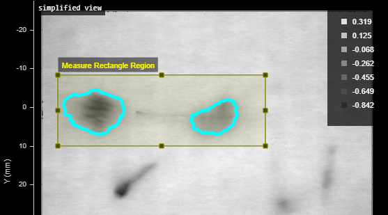
Use Measure Region |
Limits blob detection to a user-defined region. If this option is not checked, the tool detects blobs in the entire active area. In the following, blobs are only detected in the rectangular measure region:
|
|
Measure Region Type |
When you enable Use Measure Region, the tool displays this and additional settings related to the type selected in this parameter. For details on flexible regions and their settings, see Flexible Regions. For general information on regions and the difference between standard and "flexible" regions, see Regions. |
|
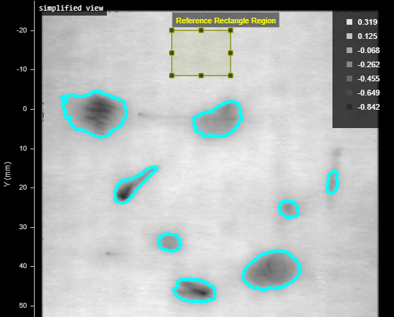
Reference Type |
Provides three options: None, Reference Region, and Reference Plane. If the reference type is set to None, the Height Threshold setting is absolute (relative to zero). For the Reference Region and Reference Plane options, see the descriptions of the Reference Region Type and Reference Plane parameters below. |
|
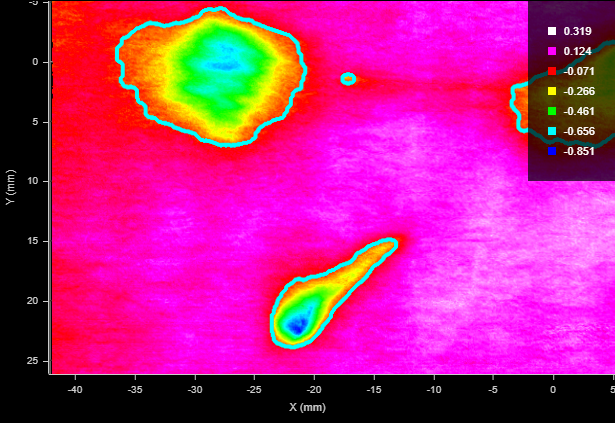
If you set Reference Type (see above) to Reference Region, the tool displays a drop-down that lets you choose the reference region type, as well as additional settings related to the type you select. (For details, see Flexible Regions.) The tool calculates an average height or intensity of the data in the reference region. Height Threshold is relative to this value. For example, in the following, blobs are detected using a relative height threshold of -0.2 mm, relative to the average in the reference region:
For general information on regions and the difference between standard and "flexible" regions, see Regions. |
|
|
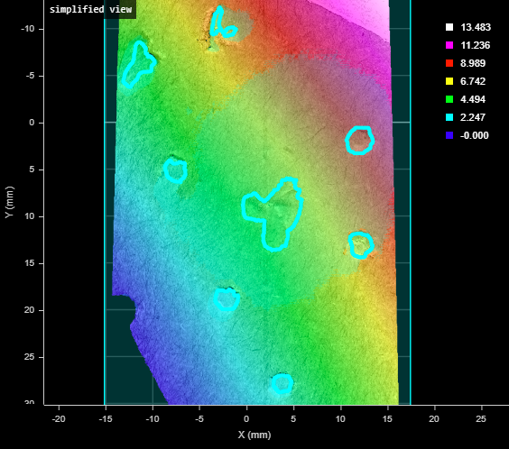
If you set Reference Type (see above) to Reference Plane, the tool uses the specified plane geometric feature to correct for a tilt of the target. Note however that using a reference plane to correct the tilt distorts the scan data: it sheers the data by the same angle as the tilt. The maximum tilt angle with which you can use the tool therefore depends on how much sheer angle you can tolerate in your application (which can effect the tool's ability to detect blobs). Typically, you add and configure a Surface Plane tool to generate a plane (for more information, see Plane). For information on geometric features, see Geometric Features. For applications where sheer distortion can't be tolerated, use Surface Transform to correct the tilt (see Transform), and use the latter tool's output as the input for Surface Blob. For example, in the following, despite the overall tilt of the target, the tool detects the flaws on the surface. (Note the gradient of the heightmap colors, indicating a height difference of roughly 9 millimeters between the lower and higher areas near the dents on the target's surface.)
|
|
|
Include Null Points |
Indicates whether null points (points where no height or intensity value is available, due to dropouts or regions outside of the measurement range) are filled with the value in Null Fill Value as a general “background level” or to fill gaps to aid in isolating blobs. If Use Intensity is enabled, the value in Null Fill Value is an intensity. |
|
Height Threshold Intensity Threshold |
The threshold above or below which data is considered for being a blob. Use the Threshold Direction setting to determine whether data above or below the threshold is considered. If Use Intensity is enabled, this setting is named Intensity Threshold. Otherwise, it is named Height Threshold. |
|
Threshold Direction |
Determines whether data above or below the threshold is considered as being a blob. Below: The Height Threshold value is the maximum that will be considered as part of a blob (for example, a dent below the surrounding surface). Above: The Height Threshold value is the minimum that will be considered as part of a blob (so a raised feature). |
|
Open Kernel X Open Kernel Y |
The X and Y kernel size, respectively, for morphological opening to remove small areas of data. Use these settings, for example, to remove bridges between areas to properly isolate them or to remove small areas entirely (perhaps caused by noise). Use different values of X and Y to use a non-rectangular filter to adapt the kernel to the kinds of unwanted data you see in the scan data. |
|
Close Kernel X Close Kernel Y |
The X and Y kernel size, respectively, for morphological closing to fill in holes smaller than the specified kernel size. Use these settings, for example, to fill small areas within potential blobs that may be caused by drop-outs. Use different values of X and Y to use a non-rectangular filter to adapt the kernel to the kinds of holes you see in the scan data. |
|
Hierarchy |
Provides options to let you find either external blobs only or both external and internal blobs. External Blobs Use this option to ignore smaller blobs in larger blobs: only the outermost blob is returned. External + Internal Blobs Use this option to include smaller blobs in larger blobs. |
|
Use Area Filter Max Area Min Area |
If Use Area Filter is enabled, the tool applies an area filter to potential blobs using the values in Max Area and Min Area. |
|
Use Aspect Filter Max Aspect Min Aspect |
If Use Aspect Filter is enabled, the tool applies an aspect filter (ratio of length and width) to the rotated bounding box that would encapsulate the area, using the values in Max Aspect and Min Aspect. For example, the following dent in a surface is included as a blob if these aspect values are set to 1 and 0.354, respectively (the rotated bounding box encapsulating would be 13.059 mm x 4.704 mm).
In the following, the same dent is excluded if Min Aspect is set to a value greater than 0.354.
|
|
Use Circularity Filter Max Circularity Min Circularity |
If Use Circularity Filter is enabled, the tool applies a circularity filter to potential blobs to measure how close to a circle the blob is, using the values in Max Circularity and Min Circularity . Circularity is determined from area within the contour of the blob and the perimeter of its contour. With increasing perimeter for the same area, circularity is reduced. |
|
Use Convexity Filter Max Convexity Min Convexity |
If Use Convexity Filter is enabled, the tool applies a convexity filter to potential blobs, using the values in Max Convexity and Min Convexity . Convexity is defined as the (Area of the Blob / Area of its convex hull), and "convex hull" of a shape is the tightest convex shape that completely encloses the shape. |
|
Ordering |
Orders the measurements, features, and surface data of the individual blobs output by the tool. Choose one of the following:
|
|
Number of Blob Outputs |
Determines the number of blobs the tool outputs as measurements, features (center points of blobs), and surface data. Currently limited to 200 blobs. |
|
Enable Z Measurements |
When this parameter is enabled, the tool outputs the minimum, maximum, and average Z value of each blob. This can be useful in applications where a large number of blobs is expected when you need these Z measurements for each one. |
|
Filters |
The filters that are applied to measurement values before they are output. For more information, see Filters. |
|
Decision |
The Max and Min settings define the range that determines whether the measurement tool sends a pass or fail decision to the output. For more information, see Decisions. |
| Anchor | Description |
|---|---|
|
X |
Lets you choose the X |
|
Z angle |
Lets you choose the Z Angle measurement of another tool to use as an angle anchor for this tool. |
|
|
A measurement must be enabled in the other tool for it to be available as an anchor. The anchor measurement should also be properly configured before using it as an anchor. |
|
|
For more information on anchoring, see Measurement Anchoring. |