Aligning Sensors with up to 5 Degrees of Freedom
For information on coordinate systems, see Coordinate Systems.
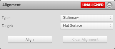
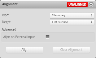
Alignment panel when Stationary Flat Surface is selected
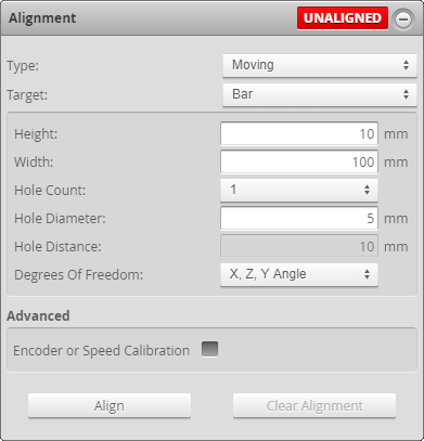
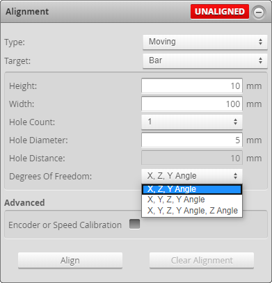
Alignment panel when Moving Bar type is selected
When using the alignment procedure on the Alignment panel, you choose an alignment type (whether the target moves relative to the sensor) and an alignment target. You choose the combination of type and target based on the types of mounting inaccuracies (mostly minor rotations of the sensor around the X, Y, or Z axis relative to the scanning surface, but also intentional rotations in some situations (such as Y rotation, which is very common), and offsets of sensors in dual- or multi-sensor systems) you need to compensate for, or the reference plane you wish to set. Gocator will calculate different transformations depending on your choice.
Sensors support two types of alignment: stationary or moving.
| Type | Description |
|---|---|
| Stationary |
Stationary is used when the alignment target does not move during the alignment procedure.
|
| Moving |
Moving is used when the alignment target moves beneath the sensor.
|


A sensor can be in one of two alignment states: Unaligned and Aligned. An indicator on the Alignment panel displays UNALIGNED or ALIGNED, depending on the sensor's state. A sensor's alignment state determines its coordinate system; for more information on coordinate systems, see Coordinate Systems.

|
If you perform a high-accuracy tool-based sensor alignment, the Alignment panel will still display UNALIGNED. This is normal. |
| State | Explanation |
|---|---|
|
Unaligned |
The sensor or sensor system is not aligned. Data points are reported in sensor coordinates. |
|
Aligned |
The sensor is aligned using the alignment procedure (described below) or by manually modifying the values under Transformation in the Sensor tab on the Scan page |
Once you have performed the alignment procedure on the Alignment panel, the calculated transformation values are displayed under Transformations in the Sensor panel on the Scan page.
|
|
If you perform a tool-based sensor alignment, the derived transformation values are not displayed under Transformations in the Sensor panel. This is normal. |
![]()
With certain types of alignment, a Degrees of Freedom setting lets you choose the axes on which offsets and rotations are calculated. If the setting is not available, only X and Z offsets, and Y angle rotation, are calculated. That is, alignment is only performed within the profile plane. When the Degrees of Freedom setting is available, it generally provides options that let you perform alignment outside the profile plane.
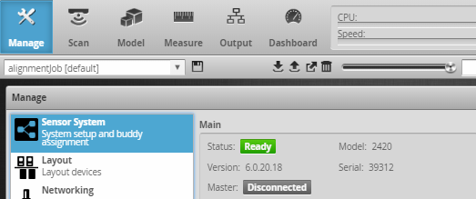
| 1. | For dual- or multi-sensor systems, make sure you have done the following: |
On the Manage page, add sensors to the system using the Sensor System category (for details, see Dual- and Multi-sensor Systems).
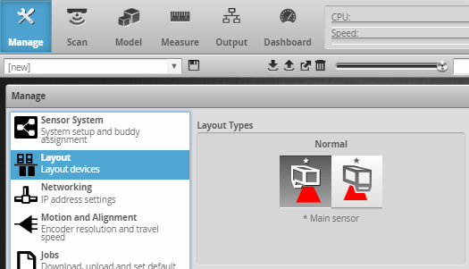
Configure the system's layout using the Layout category (for details, see Layout) .
If the laser lines of the sensors overlap, make sure to check the Device Exposure Multiplexing option (only displayed after additional sensors have been added). Otherwise, the laser line from one sensor will be detected by other sensors and cause the alignment procedure to fail or be inaccurate; for more information, see Device Exposure Multiplexing.
| 2. | If you have not already done so, choose an alignment reference in the Motion and Alignment category on the Manage page. |
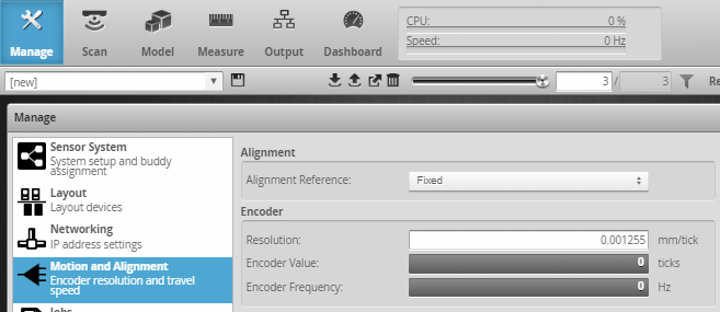
For more information, see Alignment Reference.
| 3. | Go to the Scan page. |
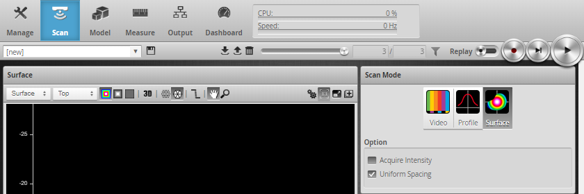
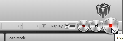
| 4. | In the Scan Mode panel (see above), choose a mode other than Video mode in the Scan Mode panel. |
The Alignment panel is hidden in Video mode. (For the alignment procedure, it doesn't matter which mode you use.)
| 5. | Leave the settings in the Trigger panel as is. |
The alignment procedure automatically uses Time triggering, regardless of the settings in the Trigger panel. (For information on triggering, see Triggers.)
| 6. | Ensure that all sensors will have a clear view of the target surface. |
| 7. | Perform a preliminary scan of the alignment target to evaluate the quality of the scan data. |
Doing this will help ensure that the alignment process succeeds. In the next step, adjust the settings based on the scan data of the alignment target.
| 8. | If necessary, in the Sensor panel, adjust the sensor settings to get the best data possible from the scans of the alignment target. |
Some examples of the settings you may need to adjust are:
- Exposure duration (to make sure the target is clearly represented in the scan data). Typically, only a single exposure is needed. For more information, see Single Exposure.
- Active area.
- Spacing:
| 9. | Expand the Alignment panel by clicking on the panel header or the  button. button. |
| 10. | Based on the decisions made in Choosing an Alignment Method, do one of the following: |
- If you need to perform a stationary alignment, see Performing Stationary Alignment.
- If you need to perform a moving alignment, see Performing Moving Alignment.
Performing Stationary Alignment
To perform stationary alignment
| 1. | In the Alignment panel, select Stationary as the Type. |
| 2. | (Optional) If a previous alignment is present (indicated by "Aligned" at the top right of the panel), click Clear Alignment. |
![]()
| 3. | Make sure that the alignment surface (whether it's the surface of a conveyor or of an alignment target) is within the sensor's measurement range. |
To determine this, in the sensor's web interface, click Start and observe whether the Range LED on the sensor is illuminated. Be sure to stop the sensor after this step by clicking the Stop button.

Alternatively, you can determine the correct distance to the scan surface by consulting the sensor's measurement range specifications (see Sensors), and measuring the physical distance between the scan surface and the sensor.
| 4. | Based on the decisions made in Choosing an Alignment Method, choose an alignment Target. |
- Flat Surface:
- Bar: Use this to align to a bar alignment target. For information on alignment target requirements, bar-specific settings, and general setup tips, see Stationary and Moving Bar.
- Polygon: Use this to align a ring layout setup using a polygon shaped alignment target. For information on alignment target requirements, polygon-specific settings, see Stationary Polygon.
| 5. | Click the Align button. |
The alignment process starts.
If the alignment fails, check the settings described in To prepare for alignment and repeat the steps described here.
| 6. | Inspect alignment results. |
Data points from all sensors should now be aligned to the alignment target surface.
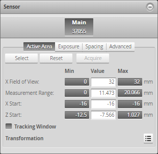
Check the alignment results under Transformation in the Active Area tab in the Sensor panel.
![]()
For information on how alignment affects the coordinate system used by sensors, see Coordinate Systems.
Performing Moving Alignment
| 1. | In the Alignment panel, select Moving as the Type. |
| 2. | If a previous alignment is present (indicated by "Aligned" at the top right of the panel), click Clear Alignment. |
![]()
| 3. | Place the target under the sensor. |
| 4. | Make sure that the surface of the alignment target is within the sensor's measurement range. |
To determine this, in the sensor's web interface, click Start and observe whether the Range LED on the sensor is illuminated. Be sure to stop the sensor after this step by click the Stop button.
Alternatively, you can determine the correct distance to the scan surface by consulting the sensor's measurement range specifications (see Sensors), and measuring the physical distance between the scan surface and the sensor.
| 5. | Based on the decisions made in Choosing an Alignment Method, choose an alignment in the Target drop-down. |
- Disk: Use this to align to a disk alignment target. For information on disk-specific settings, alignment target requirements, and general setup tips, see Moving Disk.
- Bar: Use this to align to a bar alignment target. For information on bar-specific settings, alignment target requirements, and general setup tips, see Stationary and Moving Bar.
| 6. | (Optional) If you need to calibrate the transport system, check the Encoder or Speed Calibration checkbox. |
The automatic encoder and speed calibration functionality is less accurate than manually specifying the transport system's encoder resolution or travel speed. You should only use this option if you have no other way of getting these values.
If you do not use the built-in encoder or speed calibration functionality, make sure you have done one of the following:
- If the transport system includes an encoder, make sure you have configured the encoder resolution. For more information, see Encoder Resolution.
- If the transport system does not use an encoder (it is a time-based system), make sure you have configured travel speed. For more information, see Travel Speed.
| 7. | Click the Align button. |
The alignment starts.
If the alignment fails, check the settings described in To prepare for alignment and repeat the steps described here.
| 8. | Start the transport system. |
The sensors will start and then wait for the alignment target to pass through the laser plane. Alignment is performed simultaneously for all sensors. Alignment may take a minute or more.
| 9. | Inspect alignment results. |
Data points from all sensors should now be aligned to the alignment target surface.
Check the alignment results under Transformation in the Active Area tab in the Sensor panel.
![]()
For information on how alignment affects the coordinate system used by sensors, see Coordinate Systems.
Stationary Flat Surface
No settings are required for this alignment method. Note however that this type of alignment expects to receive flat scan data. Therefore, if the surface is curved, the alignment will be inaccurate. The surface should also be clear of debris and damage.
Moving Disk
|
|
Disks are typically only used in demo systems. |
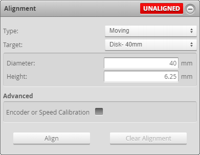
Configure the characteristics of the target. You can automatically set the diameter and height of the 40 mm and 100 mm disks available from LMI by selecting Disk - 40 mm or Disk - 100 mm from the Target drop-down. Otherwise, select Disk - Custom and provide the dimensions manually.
Diameter defines the expected diameter of the disk.
Height defines the thickness of the disk in the Z direction. The alignment determines the average Z height of the disk's top surface. This height value is used to offset the coordinate system so that the bottom of the alignment disk becomes the Z origin.
Stationary and Moving Bar
For information on bar specifications and procedural requirements, see Bar Specifications and Procedural Requirements.
For information on configuring Gocator for bar alignment, see Configuring Gocator for Bar Alignment.
|
|
The Y offset, X angle, and Z angle transformations cannot be non-zero when Uniform Spacing is unchecked. Therefore, when aligning a sensor using a bar alignment target with Uniform Spacing unchecked, set the Degrees of Freedom setting to X, Z, Y Angle, which prevents these transformations from being non-zero. |
|
|
On sensors aligned using Z angle (or sensors with a manually set X angle), and to a lesser extent Y offset, CPU usage increases when scanning, which reduces the maximum scan speed. |
|
|
Artifacts may appear in scan data on sensors aligned using Z angle or X angle if encoder trigger spacing is set too high (resulting in a low sampling rate). |
Bar Specifications and Procedural Requirements
See the following sections for bar specifications and procedural requirements (stationary or moving alignment).
Bar Specifications
Ensure the following:

-
The bar must extend beyond the outer ends of any laser line: sensors must not "see" the left or right end of the bar (relative to the direction of travel of the transport system). Alternatively, you can set the active area of sensors that can "see" the ends of the bar to exclude the ends from the scan data; for more information, see Active Area. Otherwise, although the alignment should succeed, it will not be accurate: it may result in unwanted offsets or angles in the transformations.

-
If the sensor system contains two or more sensors side by side that are not intentionally angled toward each other around the Y axis (for example, to reduce occlusions), the bar should have one hole per sensor. Hole spacing should roughly correspond to the distance between the center of the FOVs of the mounted sensors, and holes should be equidistant. Although alignment can be performed if a sensor sees more than one hole (for example, if the laser lines overlap enough), but only the hole nearest to the center of a sensor's FOV is used for that sensor's alignment.
-
If the sensor system contains two or more sensors side by side that are angled toward each other around the Y axis, a single hole should be used.

- Holes and bar edges must be as sharp as possible: avoid bevels.
- The size of the holes should be more than 10 times the X resolution of the sensor; for the X resolution of your sensor, see specifications of the sensor in Sensors.
-
Sensors must capture as little data from the inside of a hole as possible. Either countersink holes from the opposite side of the bar (if no sensors are positioned on the opposite side of the hole in a "Bottom" position), or paint the insides of the holes with a flat black paint. Otherwise, although the alignment should succeed, it will not be as accurate: it may result in unwanted offsets or angles in the transformations.
- The recommended flatness of bar targets for accurate Y angle is roughly the Z resolution rating of the sensor. If the bar target is curved, it will introduce an apparent Y angle in the sensor alignment. For sensor Z resolution, see the specifications for your sensor in Sensors.
- It is not necessary to machine the bar height to a high tolerance. Bar height can instead be controlled during measuring rather than at manufacture. Only flatness and parallelism are important. If the zero level is not critical for the measurement, then standard machining tolerances can be used. Alternatively you can machine to a low tolerance and measure the value to a high precision to save cost.
- Bar width (the dimension along Y, that is, the direction of travel) is used to calibrate the encoder or travel speed, and is unrelated to Y offset in dual- or multi-sensor systems.
- Bars should be painted with flat light grey or white paint to improve data capture (by reducing the possibility of reflections and improving profile data of the bar surface). Doing this also allows you to reduce the exposure to further reduce the possibility of sensors seeing the interior of a hole. Note that when performing alignment, typically, sensors only need a Single exposure, regardless of whether sensors are going to be configured to use Dynamic or Multiple exposure when scanning in production. For more information on exposure, see Exposure.

Stationary Bar: Visibility of holes and bar
The hole closest to the center of each sensor's field of view is used for the alignment procedure.
Each laser line must cross the center of a hole.
To do this:
| 1. | Advance or back up the transport system until the sensor laser line falls on the center of the hole. |
| 2. | Continue with step 3 in To perform stationary alignment. |
Moving Bar: Visibility of holes and bar
No other edges than the long edges of the bar should be visible during the alignment procedure: if sensors capture data from a conveyor or other structural component, or even debris, edges from these items may be misinterpreted as bar edges, and alignment will result in a false Y offset. Adjust the active area of sensors that see any of these items to prevent them from affecting the alignment; for more information, see Active Area.
Sensors may either see both the bar surface and the surface the bar is on, or only the bar surface (that is, if the supporting surface is beyond the sensor's measurement range): this has no impact on the alignment procedure.
Configuring Gocator for Bar Alignment
Configure the characteristics of the target (bar dimensions and reference hole layout); for more information on these settings, see below.

For an illustration of the various settings, see above.
- Height: The alignment procedure determines the average Z height of the alignment target's top surface and uses the value specified in Height to offset the coordinate system from that average Z height; in effect, the bottom of the alignment target becomes the Z origin (the zero reference level).
- Width sets the width of the bar in the Y direction. This value is only used to calibrate encoder resolution and travel speed in conjunction with the Encoder or Speed Calibration setting; for more information, see Encoder Calibration. A width of 100 mm is typical; the width is unrelated to any Y offset between sensors in dual- or multi-sensor systems.
- Hole Count is the number of holes in the bar. In a dual-sensor system, you set this manually in the Alignment panel to the number of holes in the bar. In a multi-sensor system, the number of holes in this panel is automatically set to the number of columns you enable when configuring a Grid system layout, in the Layout category on the Manage page; for more information, see Layout.
- Hole Diameter is the diameter of the holes.
- Hole Distance is the distance between the centers of the holes. This measurement is critical: you should measure this distance to within the sensor's X resolution. However, you can also machine the bar to a lower tolerance and measure the true spacing.
- In stationary bar alignment, under Degrees of Freedom, only one option is provided, namely, X, Z, Y Angle. This alignment method produces a Y angle correction, and calculates X and Z offsets.
- In moving bar alignment, under Degrees of Freedom, three options are available, which are combinations of different types of alignments. X, Y, and Z compensate for offsets on the X, Y, and Z axes, respectively. Y Angle and Z Angle compensate for rotation around the Y and Z axes, respectively. Compensating for X angle rotation is currently only possible by manually setting the rotation in the Transformations panel.
Stationary Polygon
Polygon target alignment is typically used when you need to scan 360 degrees around a target. A polygon target can also be used with an "arc" of sensors.
Polygon Target Specifications
Ensure the following:
- The target must have one corner per sensor.
- Corners must have sharp edges and should be as close to 90 degrees as possible (unless the system layout prevents using 90-degree angles).
- The surface adjacent to the corners must be flat.
- Targets should be painted with flat light grey or white paint to improve data capture (by reducing the possibility of reflections and improving profile data of the bar surface).
- Each sensor must clearly see a corner of the polygon target.
Configuring Gocator for Polygon Alignment
To perform polygon target alignment, you must set the X and Z coordinates of each corner of the alignment target. The coordinates are relative to the target itself, and you typically set them such that the X and Z origins are at the center of the target.
To properly configure the X and Z values of each corner of the alignment target (and assign sensors to the corners), you must view the sensors and alignment target so that Y increases toward you. To determine how to view the sensors and target, refer to the coordinate system orientation information for your sensor model in Sensors, or remember that Y increases moving from the camera to the laser emitter. (If any sensors are defined as Reversed in the layout grid, use only the non-reversed sensors to determine how to view the sensors; for more information on layout grids, see Layout.) Starting with the sensor set as Main (the sensor to which all other Buddy sensor, for each corner, define the X and Z coordinates and assign the sensor that is viewing that corner, proceeding in a clockwise order. You can start with any corner.

Simplified representations of sensors. When looking at the end of the alignment target and non-reversed sensors, Y must increase toward you. In the illustration, an alignment target measuring 10 mm on each side is represented. Therefore, X and Z coordinates are + or - 5 mm.
You can use the serial numbers of the sensors in the layout grid in the Layout category on the Manage page (left in the following) to help populate the fields in the Alignment panel (right).
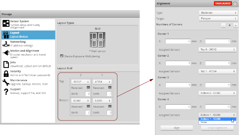
You are not required to assign a sensor to every corner.